Radio controlled bicycle back light
| Project Radio controlled Bicycle back light | |
|---|---|
| |
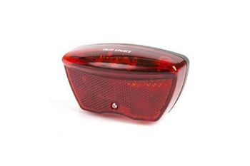
| A battery powered bicycle back light that can be used to find your bike. | |
| Status | Initializing |
| Contact | Mahjongg |
| Last Update | 2018-03-07 |
My nephew asked me if I could help him design a school project, a bicycle back light that could be remotely controlled to blink and emit sound.
I engineered a solution around a 315MHz receiver.
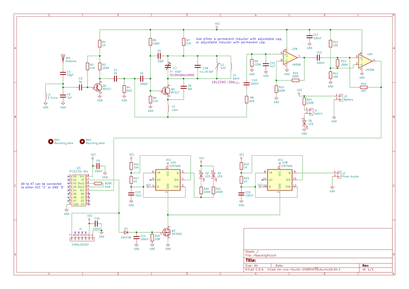
This is the (updated to rev 2.1) schematic.
File:RF Achterlicht rev2.1.pdf
31 January, 2018, made component placement
Also updated the schematic: File:Rf achterlicht rev 2,2.pdf this is the component placement drawing as a .PDF : File:Componenten opstelling rf backlight rev 2,2.pdf
this is a 3D rendering of the PCB with the latest component placement, and now also layout.
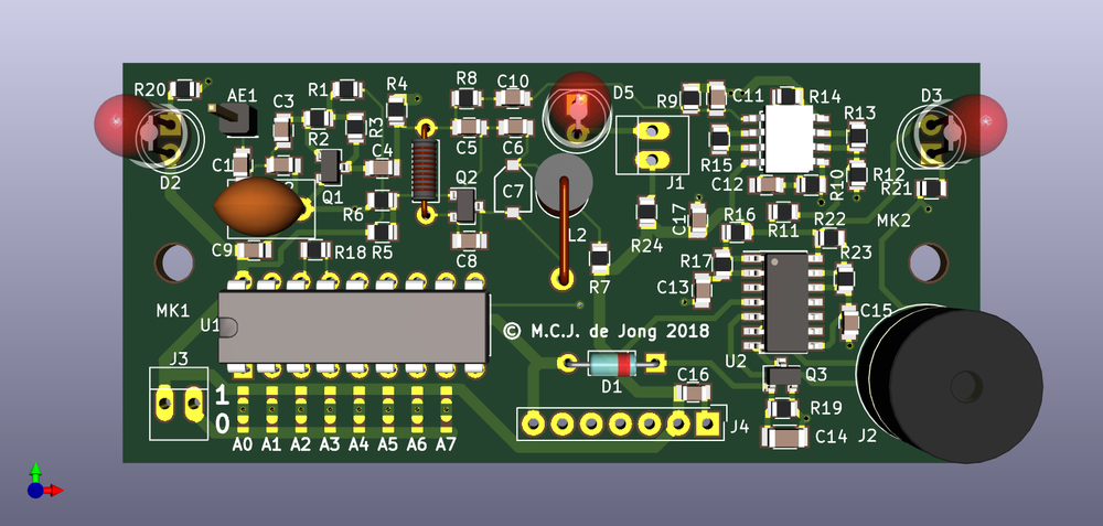
J1 connects to the manual on switch J2 connects to the piezo buzzer (now mounted on the PCB) J3 connects to the 3V battery J4 is an optional connection to a commercial 315MHz receiver (for testing).
13 February 2018, made the layout
Added a buzzer (type ABT-407-RC) 12mm round, 6.5mm pin pitch 5.5mm high) moved main LED up to top of PCB Moved mounting holes to 66mm interval added all the copper traces and copper planes created gerber and drill files, and new 3D view. The above 3D picture is now updated, refresh your browser screen if you don't see the buzzer.
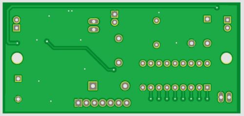
Here are pictures of the PCB, left topside, right bottom side. Now with silk screen printing, and with the added static cap and SMT coil of version 2.3
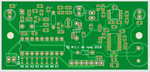
20 February 2018, added final touches
Added silk screen printing, with on silk screen indications for address data for A0 to A7, and copyright text. Changed diode from 1N4007 type to 1N4148 type. updated .PDF and 3D picture (refresh screen if you don´t see it).
Note the eight solder patch locations with which you can configure the "address" of the receiver, underneath the big decoder chip on the bottom left.
6 March, 2018, calculated LC resonance values
Calculated the values for the L and C of the 315MHz resonance circuit with f= 1/(2 * PI * SQR(L*C)) . Using a trim-cap trimable between 3 and 10pf, (a TZC3R100A110R00 Farnell code 2456140 ) I estimate the average capacity at 6.5pf, meaning the inductance should be about 39nH (see resonance calculator here: http://www.1728.org/resfreq.htm ). I now also found a suitable 39nH coil, (Coilcraft 1812SMS-39NJLC, farnell code 2287131) so I have added a SMT footprint for it. I will also add a footprint for a 0603 cap underneath the trimcap, so I can replace the trim-cap with a fixed one if I want to use a trimable coil instead of a trimable cap.
The new schematic is File:Rfachterlicht rev 2.3.pdf (revision 2.3). The PCB above now shows version 2.3.
