Radio controlled bicycle back light: Difference between revisions
| Line 68: | Line 68: | ||
As for the receiver, after attaching an oscilloscope to the pin 1 opamp output, I was able to adjust the trimcap, after extending the antenna, and holding the key chain button very close I could see a steady repeatable pattern, of pulse trains, during the trimming the decoder once detected the correct patter, as the bicycle light went off, But afterwards I could not repeat this fact, even though I managed to get a visibly cleaner pattern, it was never recognized by the PT2070-4 chip. at one time I thought the clock the chip was running at was wrong, and after measuring the original, I discovered it was generating a 27KHz clock, while mine were clocking at some 16KHz, but after checking the resistance of R18, I had made no mistake, and both were using 820K | As for the receiver, after attaching an oscilloscope to the pin 1 opamp output, I was able to adjust the trimcap, after extending the antenna, and holding the key chain button very close I could see a steady repeatable pattern, of pulse trains, during the trimming the decoder once detected the correct patter, as the bicycle light went off, But afterwards I could not repeat this fact, even though I managed to get a visibly cleaner pattern, it was never recognized by the PT2070-4 chip. at one time I thought the clock the chip was running at was wrong, and after measuring the original, I discovered it was generating a 27KHz clock, while mine were clocking at some 16KHz, but after checking the resistance of R18, I had made no mistake, and both were using 820K | ||
According to the PTC datasheet, the oscillating frequency of the 2270 decoder must be 2 to 30 times the frequency of the 2260 encoder, so I have to measure the frequency the encoder uses. The decoded signal will also be better when the encoder isn't running too fast, so that the bit-period of the encoded signal will be relatively long (slow), but seeing that a typical PT2262 encoder frequency is between 6 and 55KHz (at 3V) it seems the frequency is already quite low (note that a PT2260 encoder typically runs at a much higher frequency, from 100 to 500 MHz). | According to the PTC datasheet, the oscillating frequency of the 2270 decoder must be 2 to 30 times the frequency of the 2260 encoder, so I have to measure the frequency the encoder uses. The decoded signal will also be better when the encoder isn't running too fast, so that the bit-period of the encoded signal will be relatively long (slow), but seeing that a typical PT2262 encoder frequency is between 6 and 55KHz (at 3V) it seems the frequency is already quite low (note that a PT2260 encoder typically runs at a much higher frequency, from 100 to 500 MHz). | ||
Note that the Princeton Technology Corp. PT2262 encoder and PT2270 decoder are obviously a clone of the Holtek original (HT12D and HT12A), it might be wise to read the Holtek datasheets too. | |||
Revision as of 18:08, 18 June 2018
| Project Radio controlled Bicycle back light | |
|---|---|

| |
| A battery powered bicycle back light that can be used to find your bike. | |
| Status | In progress |
| Contact | Mahjongg |
| Last Update | 2018-06-18 |
My nephew asked me if I could help him design a school project, a bicycle back light that could be remotely controlled to blink and emit sound. So you can find your bike in a large bicycle shed.
I engineered a solution around a 315MHz receiver.
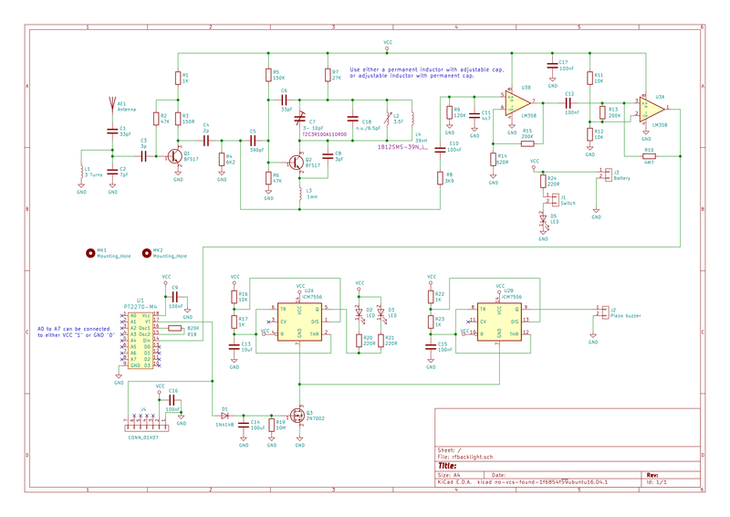
This is the (fully updated to rev 2.4) schematic.

31 January, 2018, made component placement
this is the component placement drawing as a .PDF : File:Componenten opstelling rf backlight rev 2,2.pdf
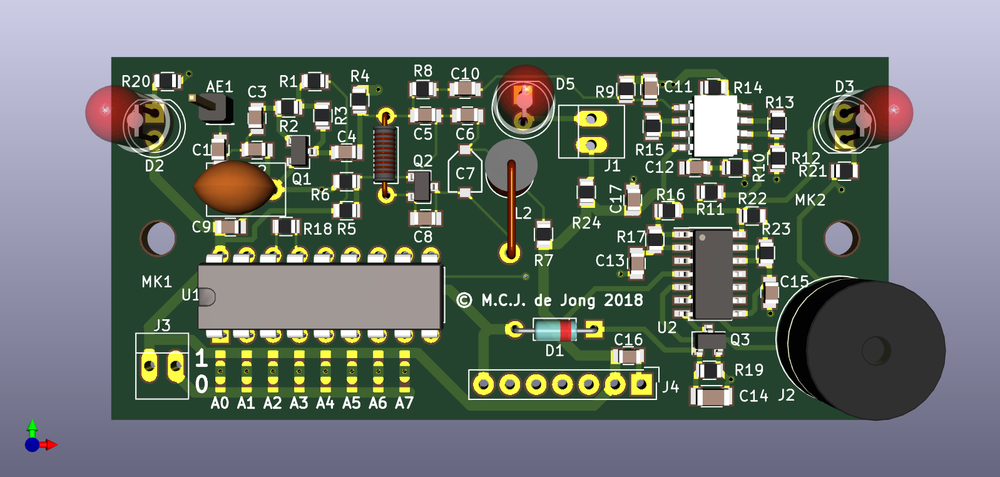
this is a 3D rendering of the PCB with the component placement and layout of version 2.2.
J1 connects to the manual on switch J2 connects to the piezo buzzer (now mounted on the PCB) J3 connects to the 3V battery J4 is an optional connection to a commercial 315MHz receiver (for testing).
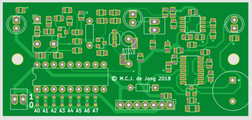
13 February 2018, made the layout
Added a buzzer (type ABT-407-RC) 12mm round, 6.5mm pin pitch 5.5mm high) moved main LED up to top of PCB Moved mounting holes to 66mm interval added all the copper traces and copper planes created gerber and drill files, and new 3D view. The above 3D picture is now updated, refresh your browser screen if you don't see the buzzer.
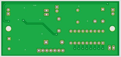
Here are pictures of the PCB, left topside, right bottom side. Now with silk screen printing, and with the added static cap and SMT coil of version 2.3

20 February 2018, added final touches
Added silk screen printing, with on silk screen indications for address data for A0 to A7, and copyright text. Changed diode from 1N4007 type to 1N4148 type. updated .PDF and 3D picture (refresh screen if you don´t see it).
Note the eight solder patch locations with which you can configure the "address" of the receiver, underneath the big decoder chip on the bottom left.
6 March, 2018, calculated LC resonance values
Calculated the values for the L and C (C7 or C18 and L3 or L4) of the 315MHz resonance circuit with f= 1/(2 * PI * SQR(L*C)) . Using a trim-cap trimable between 3 and 10pf, (a TZC3R100A110R00 Farnell code 2456140 ) I estimate the average capacity at 6.5pf, meaning the inductance should be about 39nH (see resonance calculator here: http://www.1728.org/resfreq.htm ). I now also found a suitable 39nH coil, (Coilcraft 1812SMS-39NJLC, farnell code 2287131) so I have added a SMT footprint for it. I will also add a footprint for a 0603 cap underneath the trimcap, so I can replace the trim-cap with a fixed one if I want to use a trimable coil instead of a trimable cap.
The new schematic is File:Rfachterlicht rev 2.3.pdf (revision 2.4). The PCB above now shows version 2.4.
April 4, 2018, uploading the production files to Eurocircuits failed
Unfortunately the PCB did not check out when we tried to upload it at Eurocircuits (the PCB manufacturer) Due to some last minute changes. One trace was not connected to the non-trimmable coil Pad, and there were a few via's that did not have enough metal round their holes. I also see a via that doesn't seem to serve a purpose. Initially I thought I could do the repairs on Sunday the 8th, but for some reason that weekend my Asthma became so bad that had no energy at all so I had to stay indoors, perhaps as a result of pollen combined with air pollution. I now hope to do the repairs next Tuesday the 10th.
April 10, 2018, finished PCB
Found the problematic via's were not assigned to GND, so were not connected to the ground plane on the solderside. Not getting a warning about that is IMHO a bug in KiCad's design rule checks. Fixed all layout problems (I think).
April 13, 2018, PCB ordered, parts are in
Today my nephew ordered a few PCB's, the parts for them were already ordered and have arrived. When the PCB's arrive (in seven working days) we can start assembling them.
June, 5, 2018, Finished assembly with the last missing parts
With R19, and C14 the very last parts were soldered to the two test-boards. I lowered R19 to 1M from 10M, as it seemed that after filing C14 the device never stopped blinking and making noise. With R19 as 1M the device, after filling C14 with 3 Volt, blinked and made sound for some 30 seconds, near the end the blinking became more rapid, then so rapid that you could not see it blinking, and ending with slowly going out. I put the buzzer on a small end of twisted wire, so I could also connect its + end to the output without blocking the screw, and so that I could put a 10uF elco in series with it, which made the sound a bit louder, the beep warbles a bit in the rhythm of the blinking.
As for the receiver, after attaching an oscilloscope to the pin 1 opamp output, I was able to adjust the trimcap, after extending the antenna, and holding the key chain button very close I could see a steady repeatable pattern, of pulse trains, during the trimming the decoder once detected the correct patter, as the bicycle light went off, But afterwards I could not repeat this fact, even though I managed to get a visibly cleaner pattern, it was never recognized by the PT2070-4 chip. at one time I thought the clock the chip was running at was wrong, and after measuring the original, I discovered it was generating a 27KHz clock, while mine were clocking at some 16KHz, but after checking the resistance of R18, I had made no mistake, and both were using 820K According to the PTC datasheet, the oscillating frequency of the 2270 decoder must be 2 to 30 times the frequency of the 2260 encoder, so I have to measure the frequency the encoder uses. The decoded signal will also be better when the encoder isn't running too fast, so that the bit-period of the encoded signal will be relatively long (slow), but seeing that a typical PT2262 encoder frequency is between 6 and 55KHz (at 3V) it seems the frequency is already quite low (note that a PT2260 encoder typically runs at a much higher frequency, from 100 to 500 MHz). Note that the Princeton Technology Corp. PT2262 encoder and PT2270 decoder are obviously a clone of the Holtek original (HT12D and HT12A), it might be wise to read the Holtek datasheets too.

