ZX81PLUS35 ZX81 clone
The ZX15 (previously called the ZX14) retro homecomputer is a much improved Sinclair ZX81 [1] clone built with the modern materials techniques and components of 2015.
it will be fully open sourced effort (but note that the original design of the ZX81 and its BASIC interpreter firmware is still owned by Amstrad)
As for now comments and questions on the design can be made here [2] (raspberry PI forum off topic section) :-)
Introduction to the ZX14/15
The ZX15 is a much improved ZX81 that people can build themselves. At the moment the PCB of the first prototype has been designed, and is ready to be tested.
The ZX14 should be fully compatible with the original ZX81, but with the following improvements over the original ZX81 :
- Includes turbo option switch giving more than double (220%) the speed of the original, with turbo LED, and dynamic turbo slide switch.
- Includes 16KB of RAM instead of the original 1K (should also support 32K mode) but should be compatible with "high resolution" software.
- RAM can be made permanent with a battery backup system (optional) so program remains even during power off
- Supports ZX81 BASIC in either a EEPROM or in an OTP (one time programmable ROM)
- Compatible with modern TV's thanks to better digital sync signal generation, giving sharp stable and high contrast pictures.
- Composite video (PAL or NTSC) output signal instead of RF signal, for even sharper picture, compatible with yellow RCA inputs, and SCART
- Wobble free real expansion connector (can be modified to be fully compatible with the ZX81) modules can fit inside ZX15 enclosure, compatible with ZX81 printer
- Uses simple microUSB chargers as power supply, with low power consumption
- Can drive a simple LCD display, and some external I/O for "stand alone" applications like driving tiny robots. Debug LED/Backlight LED support.
- Simple sound generation (full sound only when using fast mode)
- Supports a DB-9 joystick with up-down-left-right and fire, immediately compatible with games that use keyboard arrow keys (5,6,7 and 8) and 0 for "fire"
- Supports keyboard with real (moving) keys, using new keyboard overlay with holes for the keys, uses cheap 6x6mm buttons.
- More sensitive and reliable cassette tape interface (can be reliably driven by MP3 players and such)
- Includes reset button option, and power LED.
- Alternative (nicer) ZX15 font available, to replace the standard one in the ROM.
- No need for the original ULA, it is replicated with conventional logic.
- Cheap to build by using low cost components, on small dual sided PCB, with single sided assembly only.
- Design files freely available (but do note that firmware is still © Amstrad!)
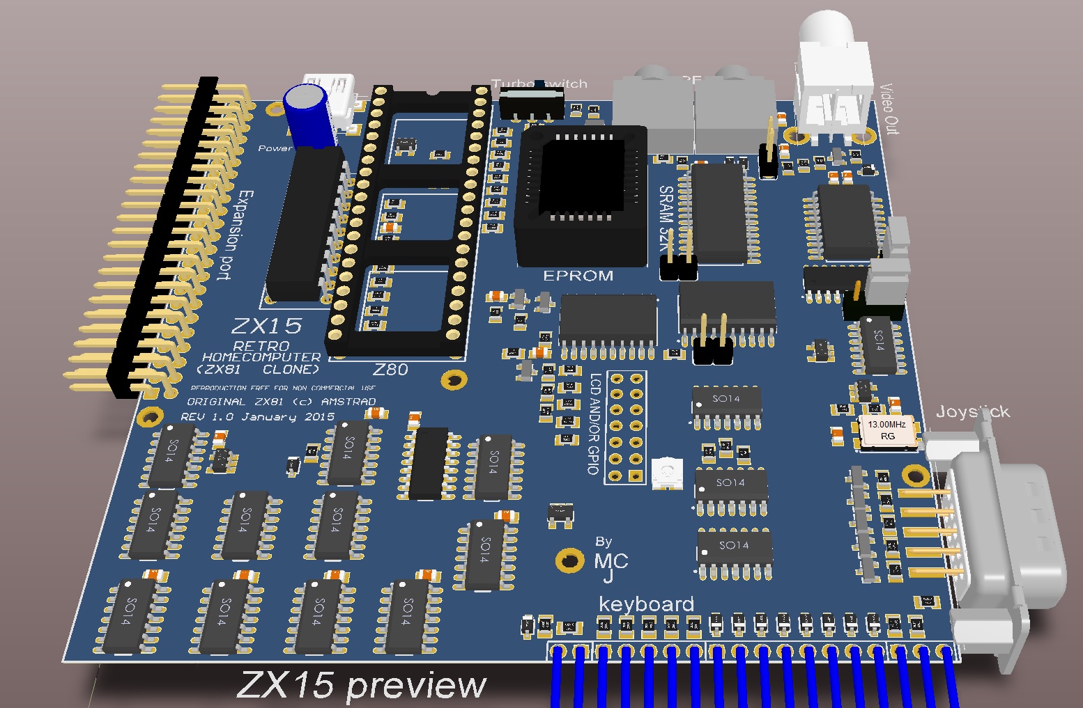
3D Preview of early ZX14
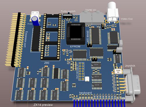
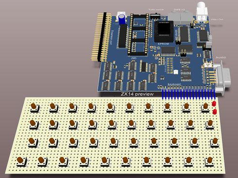
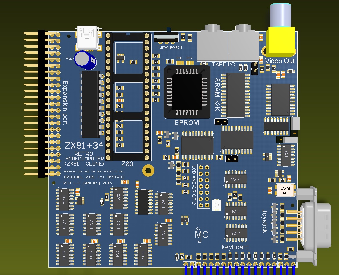
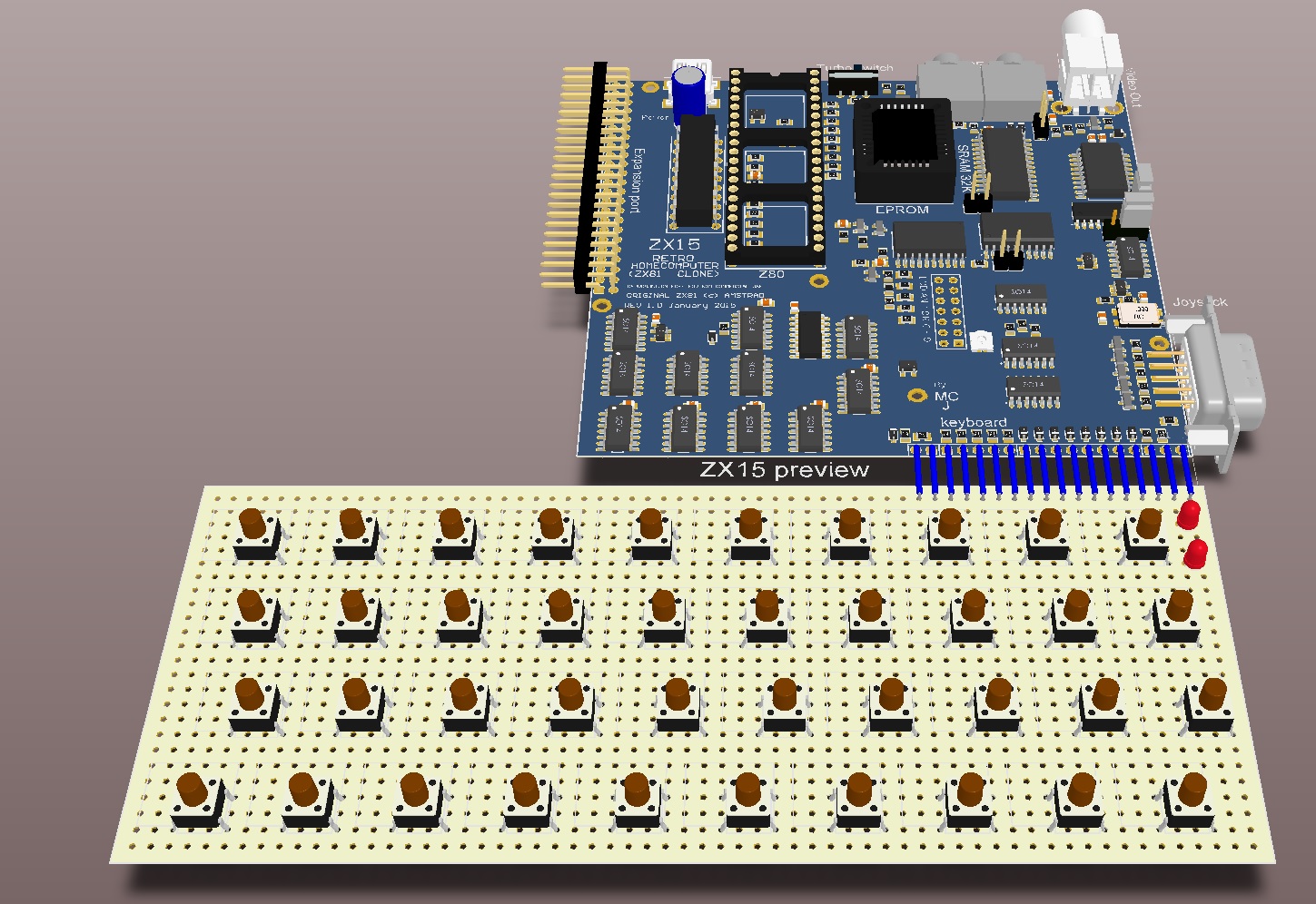
Before I even designed the PCB I made a mockup with Altium. Here are two (3D rendered) previews of the early ZX14 board, to the right a small preview of the complete system, including how I envisaged the whole system with keyboard would look like:
Schematic ZX14/ZX15
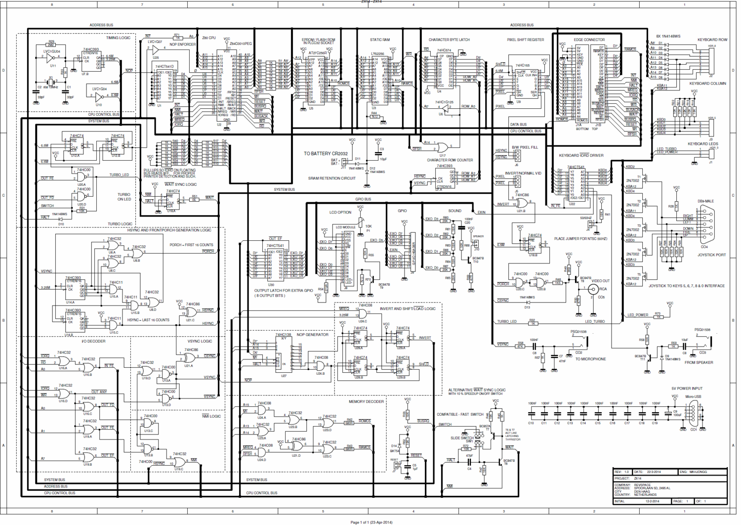
The latest schematic (.PDF) can be found here: File:ZX14 schematic.pdf There is also a color coded schematic (.PDF), it can be found here: File:Color coded ZX14 schematic with eprom support.pdf. Note that SMT components are depicted purple, and PTH ones green.
Layout ZX14
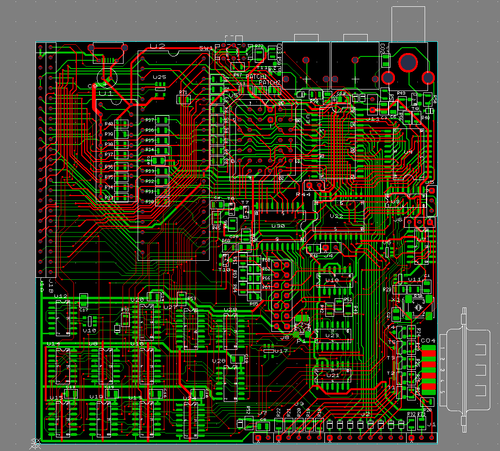
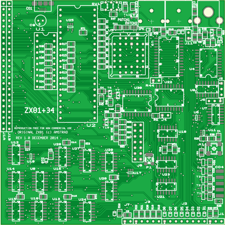
Even though I was hospitalized, then immobilized for several months (in the months of June July and August 2014) due to an operation on my leg, I still managed to work a bit on the layout of the ZX14. And on November 25, 2014 The layout work reached 100% connectivity. Here is a preview of how the work was progressed at that time . Clean-up, optimizing and copper filling followed somewhat later. The picture below on the left was actually a screen shot from a gerber viewer of how the board looked in September 16, 2014, note the lack of copper fill to make it easier to follow the connections around. Some weeks later the cleanup was ready, and this is a picture of how the PCB will more or less look like, when it is finished. Note the old PCB layout still had the, now defunct name "ZX81+34".
Keyboard (ZX14/ZX15)
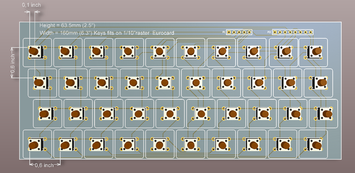
Early on I was also busy designing a solution for the keyboard. My solution was to use commercially available cheap 6x6mm buttons, which (with some effort by bending the pins a bit) can be mounted on an EuroCard sized piece of 1/10"raster perfboard, the result would like something like the picture on the left.
Here is the schematic and board layout of the keyboard: File:KB matrix schematic.pdf
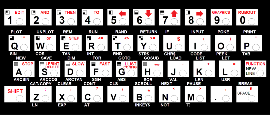
I also designed a new keyboard overlay suitable for such a keyboard with the keys going through holes in the overlay. On the right is a drawing showing how it would look, note the brown dots are actually the actuators of the push buttons going through the holes in the overlay.
Here is a .PDF version that should be correctly scaled when printed on A4 paper. You can also use it to create a replacement keyboard for your ZX81.
The ZX15
Finally early January 2015 the PCB of the ZX15 was finished, some last minute changes were made to the silk screen, and some mounting holes were added (needed to mount in an enclosure, and to connect shielding, if you want to add that)
