ZX81PLUS35 ZX81 clone: Difference between revisions
| Line 28: | Line 28: | ||
== Keyboard (ZX14/ZX15) == | == Keyboard (ZX14/ZX15) == | ||
Early on I | Early on I was also busy designing a solution for the keyboard. | ||
My solution was to use commercially available cheap 6x6mm buttons, which (with some effort by bending the pins a bit) can be mounted on an EuroCard sized piece of 1/10"raster perfboard, the result would like something like the picture on the left. | My solution was to use commercially available cheap 6x6mm buttons, which (with some effort by bending the pins a bit) can be mounted on an EuroCard sized piece of 1/10"raster perfboard, the result would like something like the picture on the left. | ||
Revision as of 02:28, 16 January 2015
The ZX15 (previously called the ZX14) retro homecomputer is a much improved Sinclair ZX81 [1] clone built with the modern materials techniques and components of 2015.
it will be fully open sourced effort (but note that the original design of the ZX81 and its BASIC interpreter firmware is still owned by Amstrad)
As for now comments and questions on the design can be made here [2] (raspberry PI forum off topic section) :-)
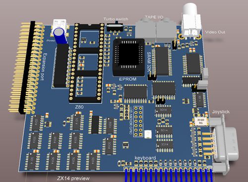
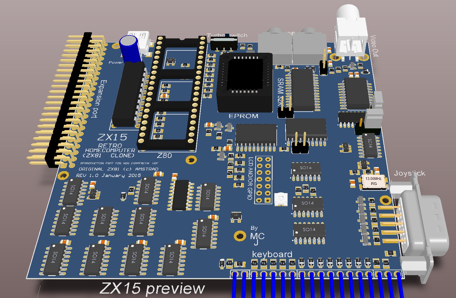
3D Preview of early ZX14
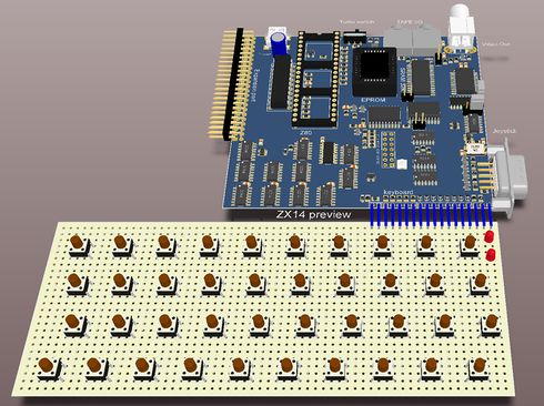
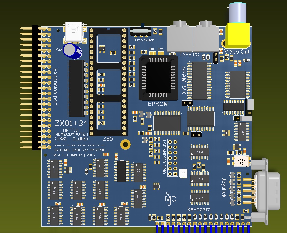
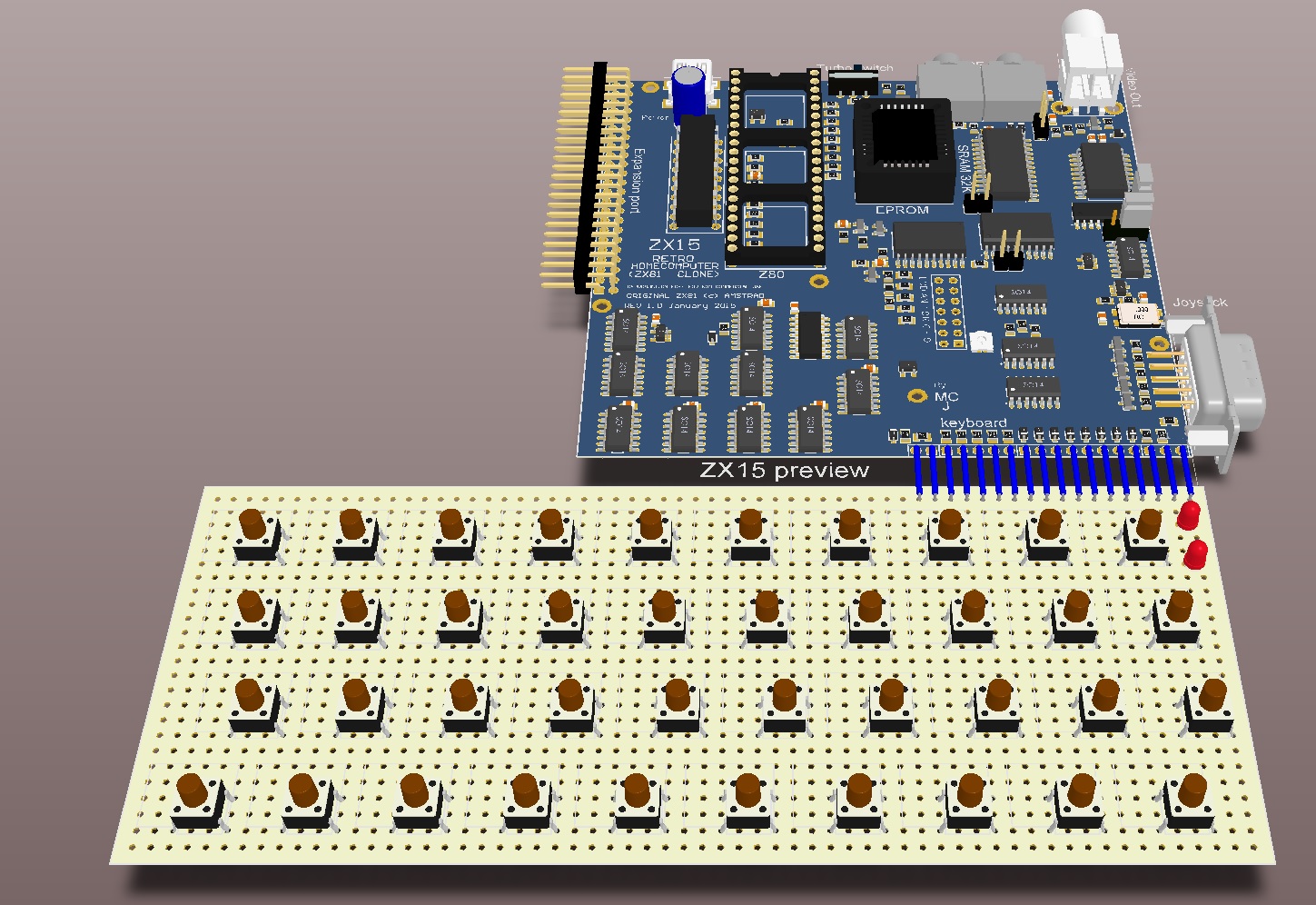
Before I even designed the PCB I made a mockup with Altium. Here are two (3D rendered) previews of the early ZX14 board, to the right a small preview of the complete system, including how I envisaged the whole system with keyboard would look like:
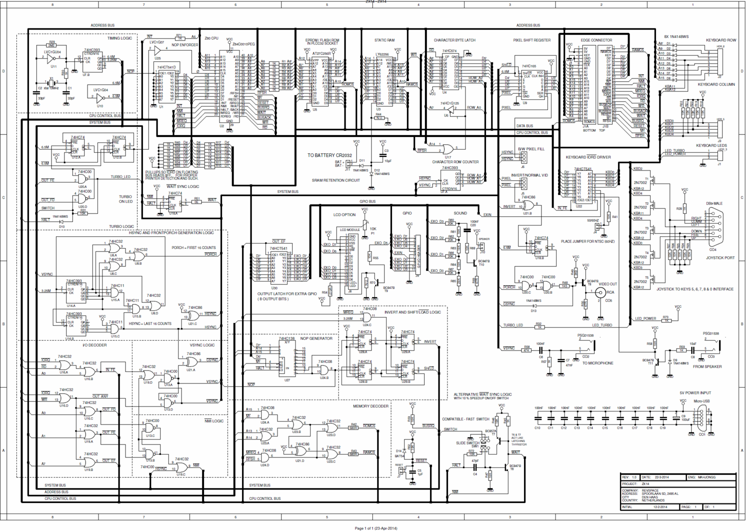
Schematic ZX14/ZX15
The latest schematic (.PDF) can be found here: File:ZX14 schematic.pdf There is also a color coded schematic (.PDF), it can be found here: File:Color coded ZX14 schematic with eprom support.pdf. Note that SMT components are depicted purple, and PTH ones green.
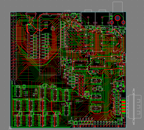
Layout ZX14
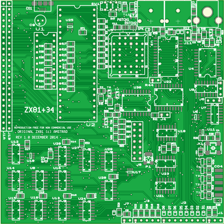
Even though I was hospitalized, then immobilized for several months (in the months of June July and August 2014) due to an operation on my leg, I still managed to work a bit on the layout of the ZX14. And on November 25, 2014 The layout work reached 100% connectivity. Here is a preview of how the work was progressing then. Clean-up, optimizing and copper filling followed somewhat later. The picture below on the left was actually a screen shot from a gerber viewer of how the board looked in September 16, 2014, note the lack of copper fill . Some weeks later the cleanup was ready, and this is a picture of how the PCB will more or less look like, when it is finished. Note the old PCB layout still had the, now abandoned name "ZX81+34".
Keyboard (ZX14/ZX15)
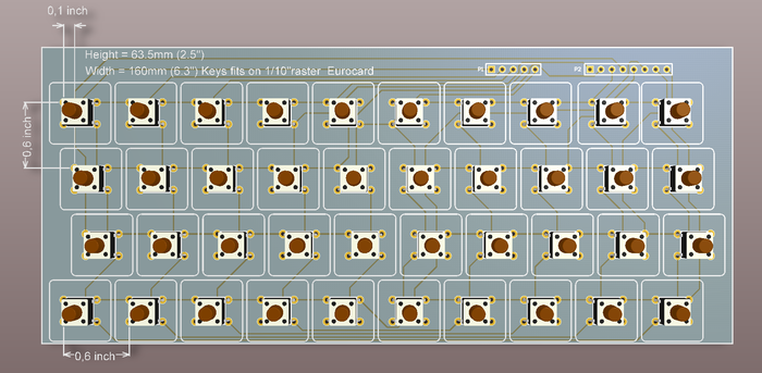
Early on I was also busy designing a solution for the keyboard. My solution was to use commercially available cheap 6x6mm buttons, which (with some effort by bending the pins a bit) can be mounted on an EuroCard sized piece of 1/10"raster perfboard, the result would like something like the picture on the left.
Here is the schematic and board layout of the keyboard: File:KB matrix schematic.pdf
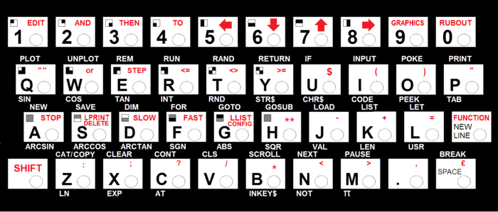
I also designed a new keyboard overlay suitable for such a keyboard with the keys going through holes in the overlay. On the right is a drawing showing how it would look, note the brown dots are actually the actuators of the push buttons going through the holes in the overlay.
Here is a .PDF version that should be correctly scaled when printed on A4 paper. You can also use it to create a replacement keyboard for your ZX81.
The ZX15
Finally early January 2015 the PCB of the ZX15 was finished, some last minute changes were made to the silk screen, and some mounting holes were added (needed to mount in an enclosure, and to connect shielding, if you want to add that)
