File:PTDC0004.JPG: Difference between revisions
Jump to navigation
Jump to search
(SNES emulator setup, PCB with buttons and pullup resistors, below a PI Zero, with pinheader on back. The button PCB is meant to be soldered onto the pinheaders.) |
(Addig to category) |
||
| Line 1: | Line 1: | ||
SNES emulator setup, PCB with buttons and pullup resistors, below a PI Zero, with pinheader on back. The button PCB is meant to be soldered onto the pinheaders. | SNES emulator setup, PCB with buttons and pullup resistors, below a PI Zero, with pinheader on back. The button PCB is meant to be soldered onto the pinheaders. [[Category:Pictures]] | ||
Latest revision as of 19:54, 2 July 2017
SNES emulator setup, PCB with buttons and pullup resistors, below a PI Zero, with pinheader on back. The button PCB is meant to be soldered onto the pinheaders.
File history
Click on a date/time to view the file as it appeared at that time.
| Date/Time | Thumbnail | Dimensions | User | Comment | |
|---|---|---|---|---|---|
| current | 23:33, 23 November 2016 | 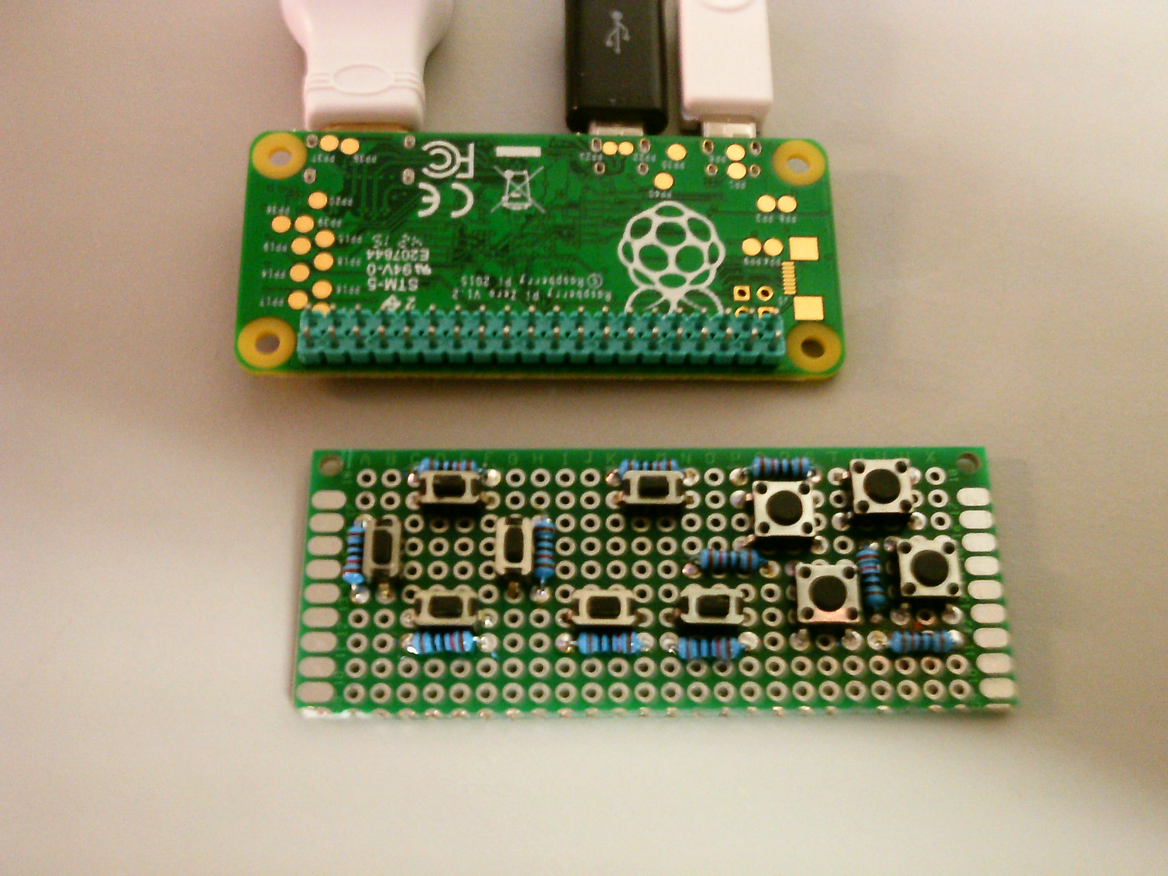 | 4,032 × 3,024 (1.92 MB) | Mahjongg (talk | contribs) | SNES emulator setup, PCB with buttons and pullup resistors, below a PI Zero, with pinheader on back. The button PCB is meant to be soldered onto the pinheaders. |
You cannot overwrite this file.
File usage
The following page uses this file: