The worlds smallest (S)NES emulator
| Project (S)NES emulator | |
|---|---|

| |
| A very tiny, (probably the smallest ever) but fully functional NES and SNES emulator based on a Raspberry PI Zero | |
| Status | Initializing |
| Contact | Mahjongg |
| Last Update | 2016-12-07 |
I tried to buy the recently released NES Classic Mini system on its launch day (the 11th of November 2016), but failed because Nintendo distributed just a very few systems worldwide, creating an immediate shortage. The largest game shop chain in the large town den Hague where RevSpace is located received just one New classic Mini for their two shops! Thats how thinly Nintendo distributed these things.
I studied what the NES Classic Mini was based on, and discovered it was actually an emulator based system, (not a direct hardware re-creation) based on an ARM system (a quadcore all winner SoC). It could take many weeks before I will be able to buy one, but I knew that for Raspberry PI's there exists an emulation system called RetroPI that is able to do the exact same thing (and then some more).
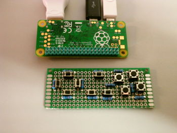
I had a raspberry PI zero left unused, and thought it would be nice to install RetroPI on it, I also knew that it would be possible to control retroPI with buttons connected to the PI's GPIO's, and a piece of code from Adafruit that converts the buttons to a "Virtual USB keyboard". Looking at my zero I envisioned that it had a shape (but not size) resembling a NES controller, and had also seen YouTube movies that described a PI zero being built into a NES controller. I decided to see if I could place buttons on a piece of perfboard that had the same size as a Raspberry PI zero, and so this project was invented, luckily I have small hands. I decided to put some extra buttons on the PCB, so it resembled a SNES controller, and added one extra button, for special functions, which may come out handy later, perhaps to be able to easily exit a game.
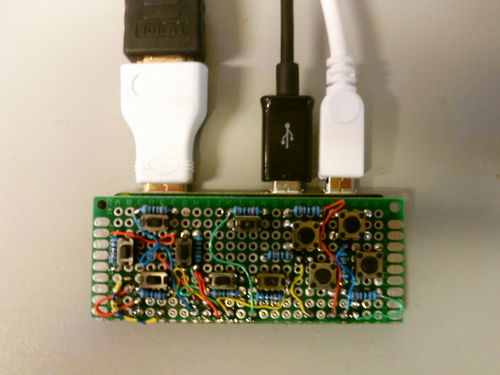
the best way to combine the button board with the PCB would not be to put the button PCB on top of the zero, but on the bottom, this would make the "stack" of the PCB's and components much thinner, so the thickness of the whole would be similar to a NES controller. First I would wire all buttons on one end to ground, with the other end of the button wired to one 10K pullup, all the other ends of the pullups would be wired together, so they could be wired to 3.3V. pack node between a button and Pullup will be wired to a single GPIO line (one not carrying a special function), at total of 11 Buttons are available, so I would need 11 GPIO's. But the zero has plenty of these. GND and 3V3 wiring was done on the bottom of the "keyboard PCB", wires running to GPIO's will be wired on top with thine wire wrap wire with at least four different colours (different from the black and red wires of the bottom.
I am planning to first solder a wire to all nodes, then to temporary wire up the GND and 3V3 wires, then use a multimeter to see if I can control each GPIO wire, so I know the wires on the bottom are Okay before soldering the PCB's together. I will place a piece of foam as isolation between the two PCB's.
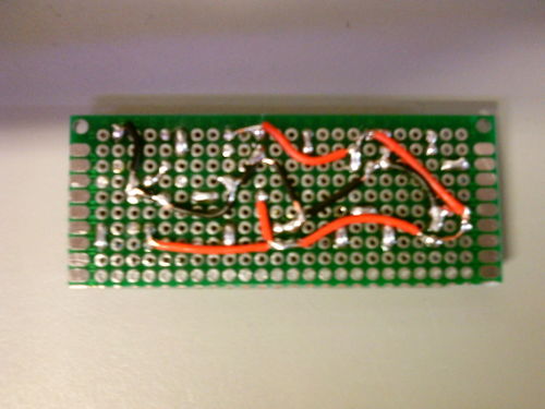
This is a picture of the wiring on the bottom of the "keyboard" PCB, showing all the GND and 3V3 wiring, and the interconnects between pullups and buttons.
note that it will be possible to also connect a full size retro NES USB controller, or a keyboard.
December 6, 2016: keypad wired up and working with RetroPI
I managed to complete the wiring of the SNES compatible keypad, and got it working with RetroPI, using the Adafruit virtual keyboard driver for RetroPI, and a dedicated configuration file.
I used another raspberry PI, a B+, in the process. Installed retroPI to a 8GB SD-card with the help of 7ZIP and WIn32Imager. When that worked (with a temporary keyboard to control it) I installed the adafruit keyboard driver, using a wired ethernet connection, and re-configured the retropi.cnf file with the GPIO ports I used for the direction keys, start, pause and A,B and X and Y keys, and an extra ESC key. Then I placed the SD-card in the zero, and configured the keyboard configurator with the assigned buttons. It took a while and I made some detours, and along the way discovered I forgot to solder a pinheader pin on the Zero GPIO side that caused the up-arrow-button to not work, but in the end it all functioned. Next Job is to get some ROM images on the sd-card, so the NES emulator is activated. For that I need to create a map on a memory stick, and put it on the booted up RetroPI system, so RetroPI can created directories for the ROM's where I can put my NES game ROM's in.
the keypad will get a white vinyl cover with lettering, to cover the wiring, and a black vinyl cross for the direction keys, and white vinyl backing over the IC's and card slot on the back, all to make it neat, and make it look like a NES controller (with extra buttons).

