The worlds smallest (S)NES emulator
| Project (S)NES emulator | |
|---|---|

| |
| A very tiny, (probably the smallest ever) but functional NES and SNES emulator based on a Raspberry PI Zero | |
| Status | Initializing |
| Contact | Mahjongg |
| Last Update | 2016-11-23 |
I tried to buy the recently released NES Classic Mini system on its launch day (the 11th of November 2016), but failed because Nintendo distributed just a very few systems worldwide, creating an immediate shortage. I studied what the NES Classic Mini was based on, and discovered it was an emulator, based on an ARM system (quadcore all winner SoC). It could take many weeks before I will be able to buy one, but I knew that for Raspberry PI's there exists an emulation system called retroPI that is able to do the same thing.
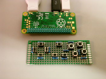
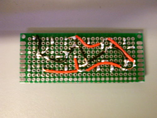
I had a raspberry PI zero, and thought it would be nice to install retroPI on it, I also knew that it would be possible to control retroPI with buttons connected to the PI's GPIO's, and a piece of code from Adafruit that converts the buttons to a "Virtual USB keyboard". Looking at my zero I envisioned that it had a shape (but not size) resembling a NES controller, and had also seen YouTube movies that described a PI zero being built into a NES controller. I decided to see if I could place buttons on a piece of perfboard that had the same size as a Raspberry PI zero, and so this project was invented. the best way to combine the button board with the PCB would not be to put the button PCB on top of the zero, but on the bottom, this would make the "stack" of the PCB's and components much thinner, so the thickness of the whole would be similar to a NES controller. First I would wire all buttons on one end to ground, with the other end of the button wired to one 10K pullup, all the other ends of the pullups would be wired together, so they could be wired to 3.3V. pack node between a button and Pullup will be wired to a single GPIO line (one not carrying a special function), at total of 11 Buttons are available, so I would need 11 GPIO's. But the zero has plenty of these. GND and 3V3 wiring was done on the bottom of the "keyboard PCB", wires running to GPIO's will be wired on top with thine wire wrap wire with at least four different colours (different from the black and red wires of the bottom.
I am planning to first solder a wire to all nodes, then to temporary wire up the GND and 3V3 wires, then use a multimeter to see if I can control each GPIO wire, so I know the wires on the bottom are Okay before soldering the PCB's together. I will place a piece of foam as isolation between the two PCB's.
The picture of the wiring on the bottom of the keyboard PCB.
