Buiding up and testing the ZX81+38 revision 1,9
| Project Building up the ZX81+38 | |
|---|---|

| |
| A manual on how to build the ZX81+38 | |
| Status | Initializing |
| Contact | mahjongg |
| Last Update | 2023-05-07 |
For those planning to build the ZX81+38, note this kit is NOT suitable for people who are not proficient in soldering. The ZX81+38 is not easy to solder, the design is dense and the solder pads are smaller than in most other designs. Also you will need to have the right tools, and probably a loupe or soldering microscope. You also need to own an EPROM programmer. I suggest using the minipro TL866CS to program a 27C256 with four copies of the ZX-81.ROM file.
Make sure you use the latest files for the PCB, BOM and component overview drawing, and schematic, at this moment these are revision 1.9.
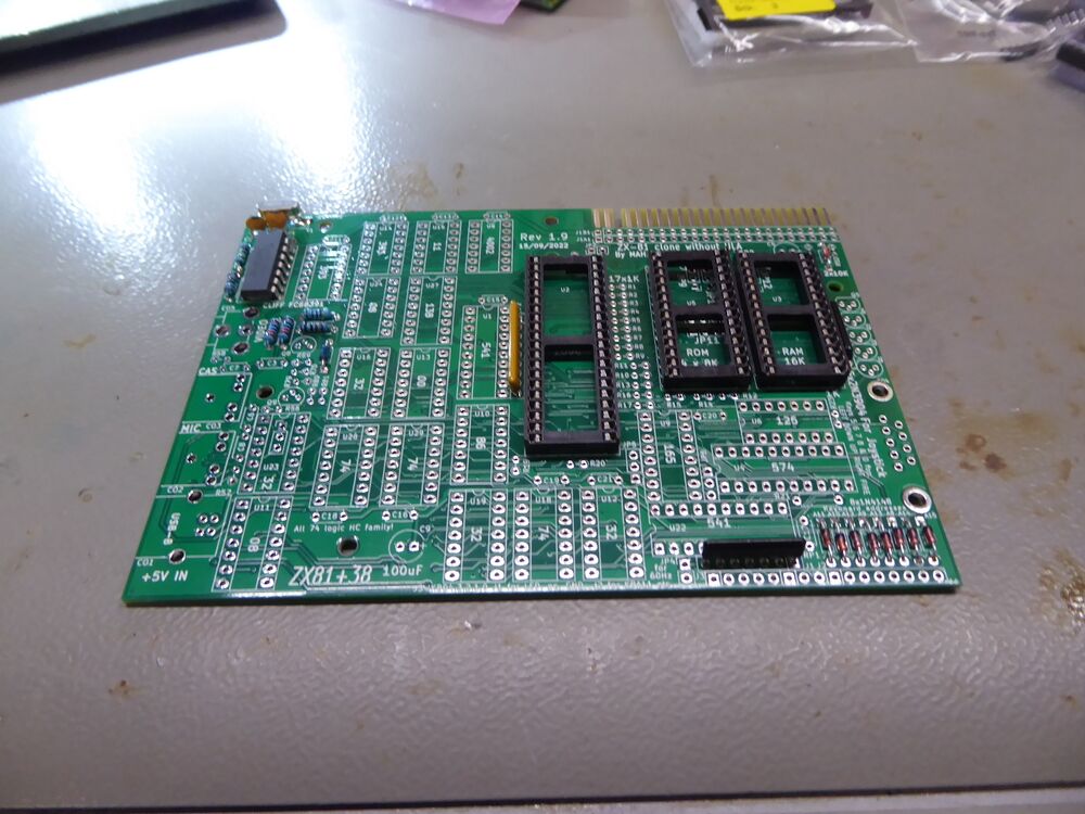
Start by soldering the lowest parts, that is , te flat lying resistors, and the resistor packs, and the diodes (the nine 1N4148 and the single skottky diode), also the three main sockets. see this picture:
Note that I'm not using sockets for the other IC's, but you can if you want, if to use dual wipe sockets, NOT round machined sockets, they are a disaster to put IC's into, and are not as reliable as they seem to be.
Then use the latest version of revision 1.9 of the component overview drawing, that is the drawing where the 15pF capacitors are BELOW the crystal. If you could not find an SMT type of this crystal, the one that comes with a plastic carrier and flat pins sticking out besides the metal can, then convert your pin though hole crystal to a SMT solderable one by sticking the pin wires through a piece of paper, fold the pins flat sideways, and cut the wires off just outside the paper isolation.then solder the pins to the solder pads beneath.
