TZXDuino pico
| Project TZXDuino Pico | |
|---|---|

| |
| building a tiny cassette recorder replacement device that can fit inside a sinclair spectrum | |
| Status | Initializing |
| Contact | mahjongg |
| Last Update | 2022-10-26 |
For the nationaal VideoGame Museum in Zoetermeer, (https://www.nationaalvideogamemuseum.nl) I'm designing a version of the TZXDuino (a cassette replacement device) that is stripped down so much that it fits INSIDE a ZX-Spectrum. A normal TZXDuino has a row of 6 or so 6x6mm buttons, and either a 16x2 character LCD (with a I2C backpack) or a tiny I2C driver graphical screen such as were used in "candy-bar" phones like the NOKIA 3310. The tiny (1 by 1 inch) OLED screen must have an I2C interface. For my application a screen was unwanted and only two buttons (Up, and Play) were needed. Also I discovered that the LM386 speaker driver used to buffer/amplify the Cassette input signal was completely unnecessary. All Barrel and jack plug connectors were replaced with simple hard wire contacts, the "autostart" connection is not used in a spectrum, but might be used in a home computer with a built in cassette deck. Like a CPC646.
As the TZXDuino Pico is not much more than a Arduino nano coupled to a SD-Card holder, it might also be used for other uses where an Arduino with sd-card interface is needed. The TZXDuino software uses a sd-card driver library, that can be used for other projects too.
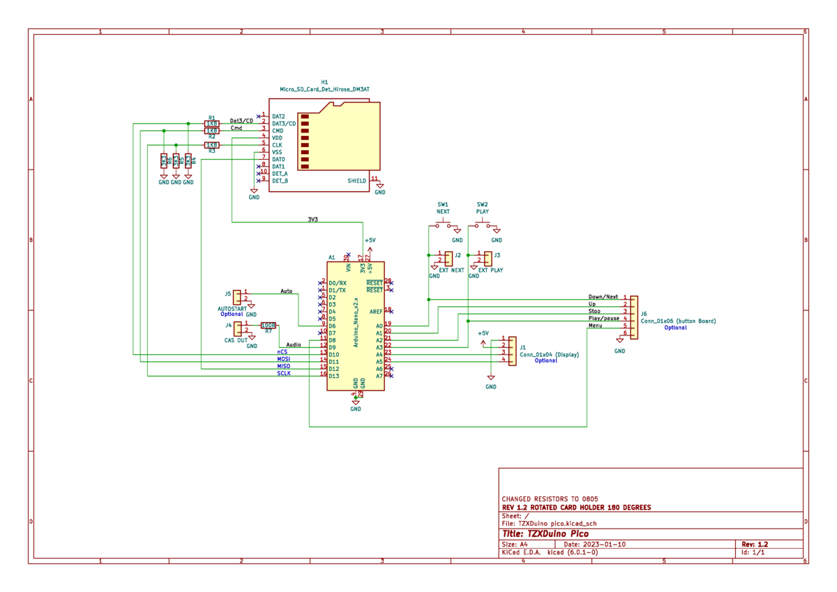
October 11, 2022 the schematic
File:TZXDuino pico schematic.pdf
I already had some DM3D-SF Hirose micro SD Push/Pull card holders, but the KiCad Library footprint of the schematic symbol for the cardholder was not an exact match to my DM3D-SF cardholders, so I used the below .PDF file that contains the exact pads of all used components to check the Footpad. when a .PDF is printed on a A4 paper it is exactly 100% correct dimensionally, so after printing the PDF (which wasn't as easy as it sounds) I could check if the pads of the footprint exactly fitted the real DM3D-SF, and luckily they did, so I can now start the layout.
To power the TZXDuino Pico, normally is done through its micro USB port, but I was planning to power it through the 5V line, but maybe it should be the VRAW input pin, I'm investigating that. If 5V is good enough I can power it through the Display connector, if powering via the VRAW pin is a necessity I have to add one more header.
October 26, 2022 did the PCB layout
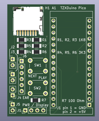
I concluded that the PCB footprint of the SD-Card holder was suitable for the DM3D-SF, and that I could power de Arduino through the 5V line, and that the Display connecter was suitable for that, as it has GND and +5V on two adjacent pins (Pin 1 and Pin 2). So I routed the PCB, and the result can be seen in the picture above. The PCB is very small less than 1.5 by 1.9 Inch. It has optionally 6x6mm buttons , but normally small pushbuttons that can be screwed to the back of the ZX-Spectrum are used and connected to J2 and J3. J2 is to switch to another game to load, and J3 is to start playback. J4 is the cassette signal output, internally connected to the EAR input jack. J5 is not used in a Spectrum, but in a computer with a built in cassette deck it can be used to autograft playing when the play button of the cassette is pressed, J6 can be used if all the buttons are used on a small button PCB, but not used in a Spectrum. The TZXDuino Pico should be compatible with the software for normal TZXDuino's. If the absence of a display is halting the software, you can try to set the display driver to "serial", I assume that then the Built into the Arduino board's serial (USB) interface will output the text that otherwise should go to the display(s). It is still possible to attach a display, either the 20 x 2 LCD, or the 1" by 1" OLED display. Both though the I2C connection. So the simple 20 x 2 LCD needs to have an I2C "backpack". The TZXDuino Pico does not have any mounting holes, one reason is that there is no place for them, and also because there is no place to mount to inside a spectrum, instead the device is mounted and electrically isolated with ducttape.
