PETDuino in Datasette: Difference between revisions
| Line 53: | Line 53: | ||
started with a (perfboard) PCB after creating a socket for the arduino nano. | started with a (perfboard) PCB after creating a socket for the arduino nano. | ||
[[File:PCB for datasette arduino.JPG| | [[File:PCB for datasette arduino.JPG|800px]] | ||
Latest revision as of 22:46, 30 July 2024
| Project PETDuino in Datasette | |
|---|---|
| |
| for my museum PET (CBM4032) I wanted to use a PET2SD floppy disk emulator, but I discovered that due to the fact that this PET has the original BASIC (rev 1,0) it doesn't support diskdrives, it doesn't have IEEE drivers, so I switched to my CBM8032 which does, but due to it 80-kolumn screen there are almost no kames working on a CBM8032!
at the moment the PET in the national video game museum in Zoetermeer is the ZX-81 game that was ported to the PET in 2021. it can be loaded from the PET2SD using the load"*",8 command. the other working game is a frogger clone. I decided to solve this conundrum by building a version of the casduino into a defective datasette. I found a fritzing diagram of a sd card reader for a CBM cassettedeck asa starter, together with the schematic of my previous TZXDuino Pico. | |
| Status | Initializing |
| Contact | mahjongg |
| Last Update | 2024-07-30 |
8 may 2024 Started with a Datasette with an Arduino and Sd-Card inside
Found a fritzing Diagram of a "casduino" for a C64/PET Datasette. Started with converting the diagram to a KiCad schematic, using the TZXDuino Pico as example, so that I don't need to use a separate SD-card interface board, or 3V3 regulator. this DATASETTE-Duino uses a 2x16 LCD with an I2C backpack..
Conversion to a KiCad schematic
I converted the fritzing diagram to a schematic, using the fritzing diagram and my earlier tzxduino. you can find a .PDF of the schematic here: File:DATASETTE-DUINO.pdf
this is a picture of the schematic:
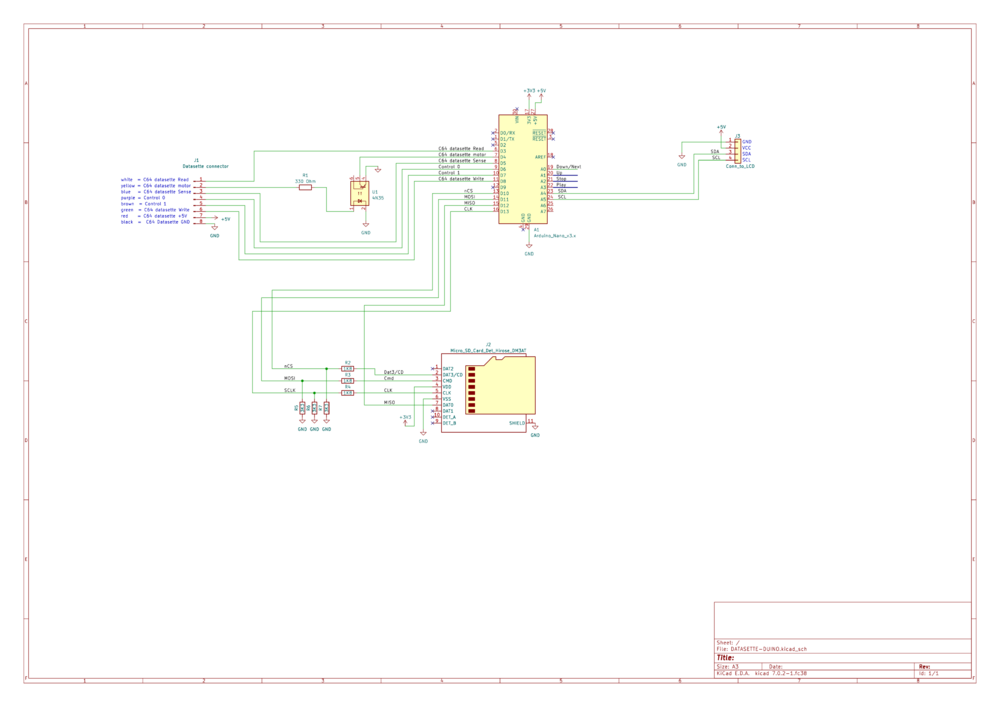
note the arduino nano pins 19 to 23 that are labelled down/next up stop and play will go to buttons or contacts corresponding to fast.forward rewind stop and play. I plan to modify the datasette so that pressing these keys will ground the corresponding pin.
Stripping the contents of the datasette
I stripped the datasette, afterwards the innards looked like this: 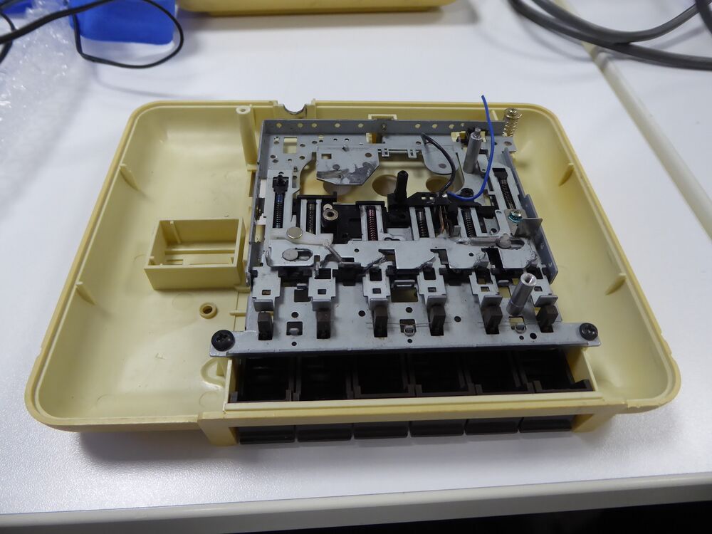
and this is what was removed from the datasette: 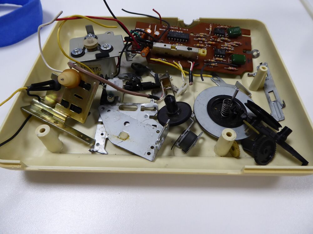
measuring the dimensions of the cassette compartment
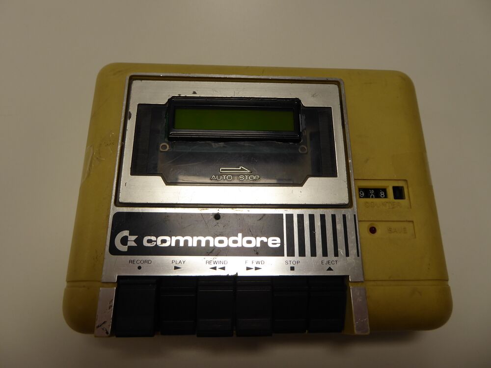
Using a calliper I measured how much room there is for the electronics in the cassette compartment. it is 117mm wide, 68mm high and 14mm deep. the display is 19mm high, so it wont fit below the datasette cover, the cover is 3mm thick. so I need to create a hole in the cover, and perhaps some plastic below the display.
Opening in tape desk cover door for LCD
As the epth of the tape deck opening was too undeep to place the LCD (with I2C) backpack under I decided to create an opening in the transparent tape deck cover door just large enough so that the metal part of the LCD could stick through it. The dimensions of the high metal part of the LCD is 71mm wide and 24mm high, so I need to create an opening in the cover with these dimensions.
Schematic of datasette duino
this is the finalised schematic of the datasette duino:
File:DATASETTE-DUINO buttons.pdf
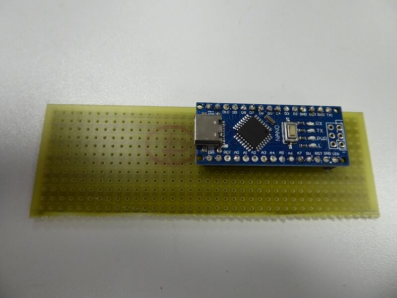
PCB for the arduino nano
started with a (perfboard) PCB after creating a socket for the arduino nano.

