TZXDuino pico: Difference between revisions
No edit summary |
|||
| Line 25: | Line 25: | ||
To power the TZXDuino Pico, normally is done through its micro USB port, but I was planning to power it through the 5V line, but maybe it should be the VRAW input pin, I'm investigating that. | To power the TZXDuino Pico, normally is done through its micro USB port, but I was planning to power it through the 5V line, but maybe it should be the VRAW input pin, I'm investigating that. | ||
If 5V is good enough I can power it through the Display connector, if powering via the VRAW pin is a necessity I have to add one more header. | If 5V is good enough I can power it through the Display connector, if powering via the VRAW pin is a necessity I have to add one more header. | ||
== October 26, 2022 did the PCB layout == | |||
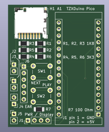
I concluded that the PCB footprint of the SD-Card holder was suitable for the DM3D-SF, and that I could power de Arduino through the 5V line, and that the Display connecter was suitable for that, as it has GND and +5V on two adjacent pins (Pin 1 and Pin 2). | |||
So I routed the PCB, and the result can be seen in the picture above. | |||
The PCB is very small less than 1.5 by 1.9 Inch. It has optionally 6x6mm buttons , but normally small pushbuttons that can be screwed to the back of the ZX-Spectrum are used and connected to | |||
Revision as of 14:35, 26 October 2022
| Project TZXDuino Pico | |
|---|---|

| |
| building a tiny cassette recorder replacement device that can fit inside a sinclair spectrum | |
| Status | Initializing |
| Contact | mahjongg |
| Last Update | 2022-10-26 |
For the nationaal VideoGame Museum in Zoetermeer, (https://www.nationaalvideogamemuseum.nl) I'm designing a version of the TZXDuino (a cassette replacement device) that is stripped down so much that it fits INSIDE a ZX-Spectrum. A normal TZXDuino has a row of 6 or so 6x6mm buttons, and either a 16x2 character LCD (with a I2C backpack) or a tiny I2C driver graphical screen such as were used in "candy-bar" phones like the NOKIA 3310. The tiny (1 by 1 inch) OLED screen must have an I2C interface. For my application a screen was unwanted and only two buttons (Up, and Play) were needed. Also I discovered that the LM386 speaker driver used to buffer/amplify the Cassette input signal was completely unnecessary. All Barrel and jack plug connectors were replaced with simple hard wire contacts, the "autostart" connection is not used in a spectrum, but might be used in a home computer with a built in cassette deck. Like a CPC646.
As the TZXDuino Pico is not much more than a Arduino nano coupled to a SD-Card holder, it might also be used for other uses where an Arduino with sd-card interface is needed. The TZXDuino software uses a sd-card driver library, that can be used for other projects too.
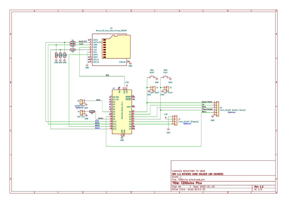
October 11, 2022 the schematic
File:TZXDuino pico schematic.pdf
I already had some DM3D-SF Hirose micro SD Push/Pull card holders, but the KiCad Library footprint of the schematic symbol for the cardholder was not an exact match to my DM3D-SF cardholders, so I used the below .PDF file that contains the exact pads of all used components to check the Footpad. when a .PDF is printed on a A4 paper it is exactly 100% correct dimensionally, so after printing the PDF (which wasn't as easy as it sounds) I could check if the pads of the footprint exactly fitted the real DM3D-SF, and luckily they did, so I can now start the layout.
To power the TZXDuino Pico, normally is done through its micro USB port, but I was planning to power it through the 5V line, but maybe it should be the VRAW input pin, I'm investigating that. If 5V is good enough I can power it through the Display connector, if powering via the VRAW pin is a necessity I have to add one more header.
October 26, 2022 did the PCB layout
I concluded that the PCB footprint of the SD-Card holder was suitable for the DM3D-SF, and that I could power de Arduino through the 5V line, and that the Display connecter was suitable for that, as it has GND and +5V on two adjacent pins (Pin 1 and Pin 2). So I routed the PCB, and the result can be seen in the picture above. The PCB is very small less than 1.5 by 1.9 Inch. It has optionally 6x6mm buttons , but normally small pushbuttons that can be screwed to the back of the ZX-Spectrum are used and connected to
