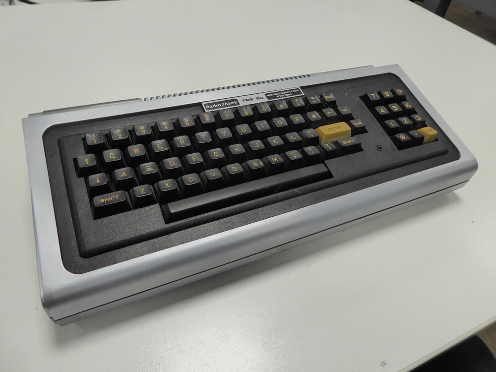
Museum readying a TRS-80 model-1: Difference between revisions
| (15 intermediate revisions by the same user not shown) | |||
| Line 49: | Line 49: | ||
here you can see the front, not the white spot where the silver paint was completely rubbed off is completely gone. | here you can see the front, not the white spot where the silver paint was completely rubbed off is completely gone. | ||
Note the blue stickers that mark that this is a project of mine, and since when it is stored in storage. | |||
[[File:TRS-80 painted TOP.JPG|1000px]] | [[File:TRS-80 painted TOP.JPG|1000px]] | ||
seen from the back you can see that the broken off "rib" is repaired. | seen from the back you can see that the broken off "rib" is repaired and you can barely notice that it was ever broken off. | ||
[[File:TRS-80 back and bottom.JPG|1000px]] | |||
== The mother board == | |||
looking at the TRS-80 Motherboard you can see that it was extensively repaired and modified. | |||
The mother board is mounted inside the case with the components hanging down on the board, so that the keyboard can rest on the bottom of the PCB with some wide round rubber standoffs. One modification that is immediately obvious is that that the short FLEX-PCB connection between the Motherboard amd the keyboard PCB. A known weakness in the design of the TRS-80 is a broken connection cable between the main and keyboard PCB. The previous owner aware of this problem has decided to take drastic actions, and replaced the short and breakabl cable with a much longer and more supple flexcable. | |||
[[File:TRS-80 motherboard bottom side.JPG|1000px]] | |||
== Memory == | |||
A normal TRS-80 main mother board contains 16K DRAM, and needs and "expansion interface" to add another two banks of 16K DRAM chips for the 48K RAM that BASIC 2 expects. | |||
the previous user probably did not want to buy the very expensive expansion interface and knew that it was possible to replace the uPD4116 16K x 1-bit with uPD4164 64K x 1-bit chips. I knew that this could be done because I have modified dozens of TRS-80 model 1 computers myself in the early 80's. because the uPD4116's use thre different voltages, and the more modern uPD4164's use only +5V, you have to remove some decoupling caps, and wiring . | |||
You can see the patch wiring for this patch from the solder-side of the PCB: | |||
[[File:TRS-80 motherboard TOP side.JPG|1000px]] | |||
One other problem many people opted to address is that the model-1 did not support lowercase letters, the designers chose a spare a few dimes by only using seven M2102 1K x 1-bit static RAM chips for video RAM. So a patch to install the missing RAM chip was quite common, and this user seems to have done the same thing. the small rectangular PCB seems to indicate this is the case. | |||
I have not powered up the computer yet, I want to be careful, and examine the schematics first. | |||
I noticed the main +5 TO-03 Voltage regulator seems to have overheated. And I want to be sure the main regulator the MC1723 is still okay. | |||
== Re-assembled the painted TRS-80 model 1 == | |||
I decided not to try to get this TRS-80 working again, the reasons are that there are two large obstacles, first I do not have the original monitor, and secondly I do not have the power supply brick. | |||
The first obstacle can be overcome,although the TRS-80 used a very special method to use a TV for a monitor, the TV they used had a "hot chassis", that is all touchable metal parts of the TV were directly connected to mains voltage, but because on a TV only the antenna input was touchable, and that was save because there was a very small (a few picofarad) high voltage capacitor in series, but that could not be the case for a monitor, so tandy used a special trick to isolate the high voltage fron the computer, in the monitor was a small pcb with a few opto isolators powered from the computer that dis the isolation. But I found out that you could get a composite video signal from the 5V DIN connector regardlessly. you can make a working vide cable by using pin 4 for video, and pin 5 for gnd, and use either a SCART, or the yellow video input of a composite monitor. | |||
but the power is a much larger problem the TRS-80 needs both AC and DC power. pin 2 and 4 needed 19.8V DC 0.35A but also it needed AC, 17.0V AC 1A between pins 1 and 3. I do not know the polarity of the DC. So I gave up trying to power the TRS-80 Model 1, its just a showroom model. I think it is now of museum quality, see the picture below | |||
'''One of the 1977 Trinity, the TRS-80 model I''' | |||
[[File:TRS-80 motherboard museum quality.JPG|1000px]] | |||
Latest revision as of 22:48, 1 October 2024
| Project Museum readying a TRS-80 model 1 | |
|---|---|
| |
| In 1977 the very first homecomputers came on the market, early in 1977 the Commodore PET 2001, a few months later the Apple 2, and at the end of the year the Tandy Radio Shack the TRS-80 Model 1, the cheapest of the three, and according to many the most useful of the "trinity" as the popular computer magazine Byte called the three in 1995. | |
| Status | Initializing |
| Contact | mahjongg |
| Last Update | 2024-10-01 |
The trinity in the Dutch National video game museum
The NaVGM (National Video Game Museum) in Zoetermeer the Netherlands has a separate room for home computers, and in there you can see (at the moment in August 2024) two of the trinity of computers, namely a PET (Personal Electronic Transactor) model CBM 8032 (this is a later european "business model" with a 80 column screen and 32K RAM, I hope to replace it with a 40 column model that is much better supported with video games, I am the owner of these two PET's) we also have an Apple ][ in a showcase. but we did not have a TRS-80 computer,until now that is. Unfortunately the TRS-80 model 1 we got has earned the name "trash-80". It looked like it has been in a trashcan for at least 30 yes.
The trinity:
From left to right the Commodore PET 2001, the Apple ][ and the Tandy TRS-80 model 1.
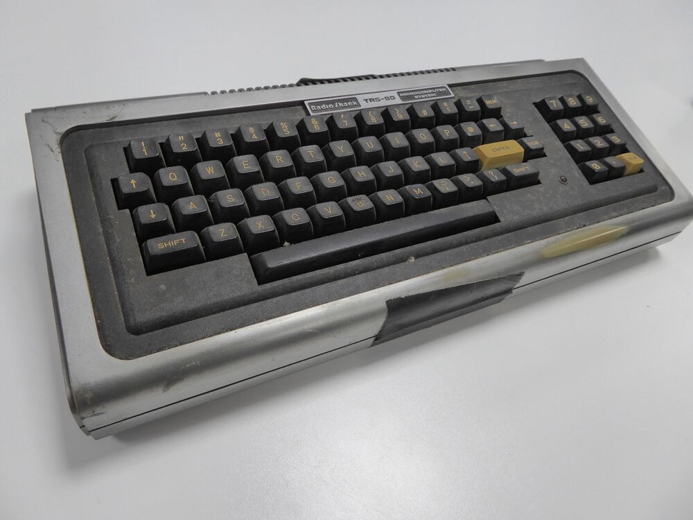
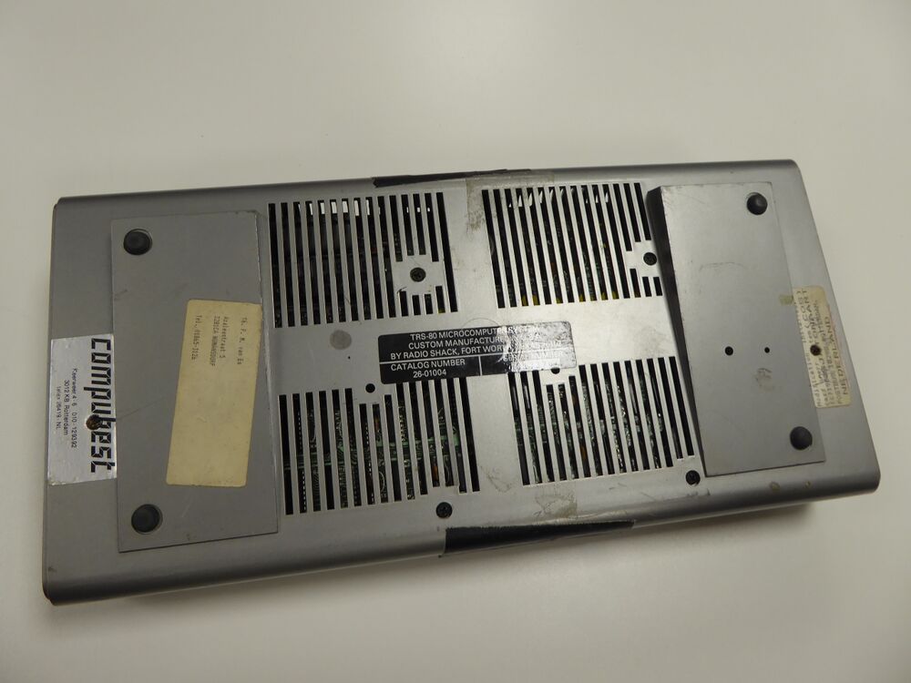
the filthy model 1: the museum received:
Top:
bottom:
bottom after sticker removal:
top after sticker removal:
as can be seen the case needs a re-paint.
I have also opened the computer, and concluded it was extensively upgraded. it seems it was upgraded to 48K of RAM, level 2 basic, and also seemed to have the lower case mod. Also the short keyboard cable was replaced with a long a flexible one.
After re-painting the Case
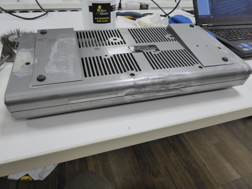
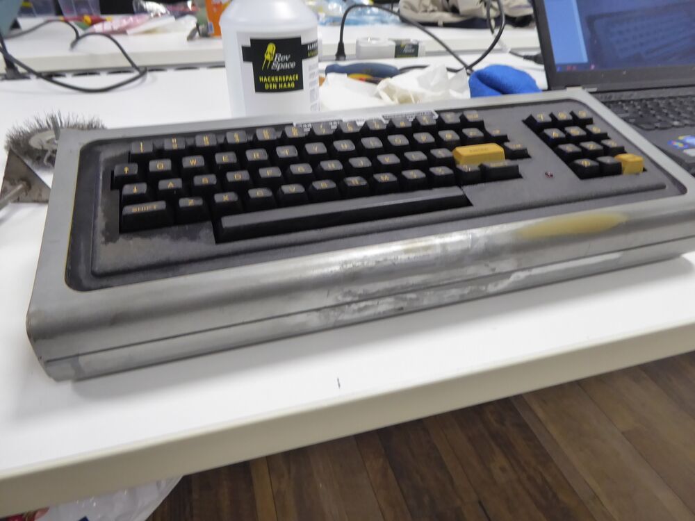
I re-painted the case, after removing all the stickers and degreasing the case with isopropanol.
I started a applying a grey primer, then after the primer had dried I applied acoating of silver spraypaint, and the result was excellent IMHO.
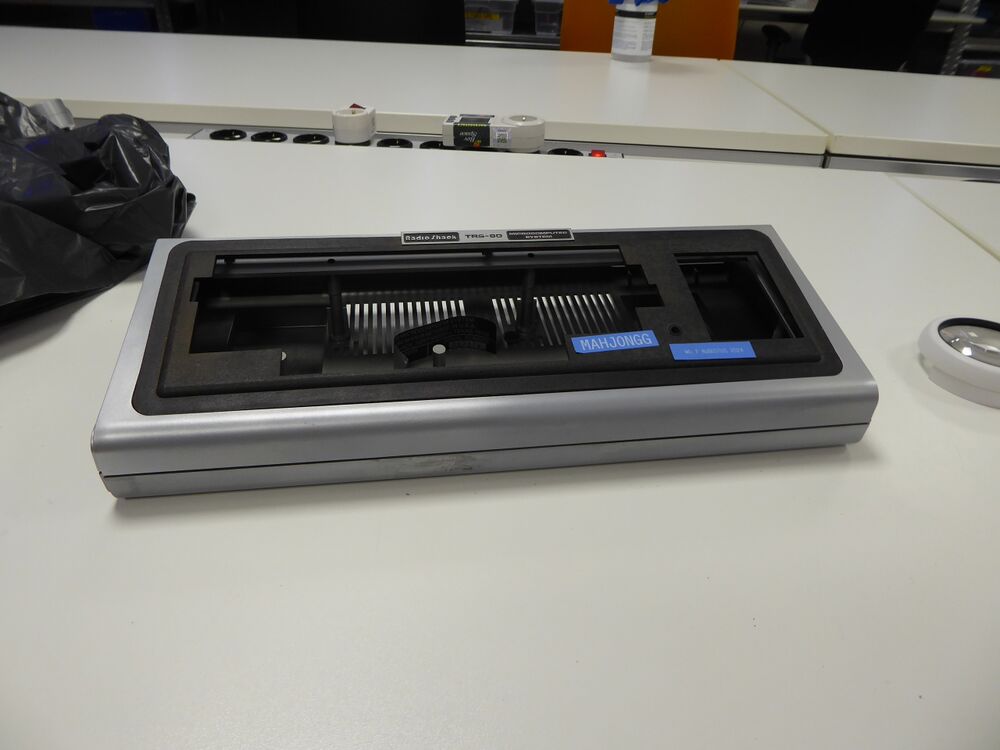
here you can see the front, not the white spot where the silver paint was completely rubbed off is completely gone. Note the blue stickers that mark that this is a project of mine, and since when it is stored in storage.
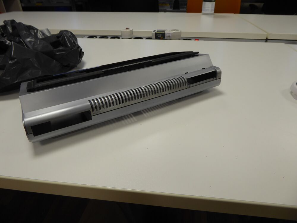
seen from the back you can see that the broken off "rib" is repaired and you can barely notice that it was ever broken off.
The mother board
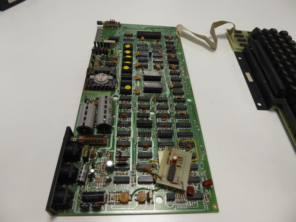
looking at the TRS-80 Motherboard you can see that it was extensively repaired and modified. The mother board is mounted inside the case with the components hanging down on the board, so that the keyboard can rest on the bottom of the PCB with some wide round rubber standoffs. One modification that is immediately obvious is that that the short FLEX-PCB connection between the Motherboard amd the keyboard PCB. A known weakness in the design of the TRS-80 is a broken connection cable between the main and keyboard PCB. The previous owner aware of this problem has decided to take drastic actions, and replaced the short and breakabl cable with a much longer and more supple flexcable.
Memory
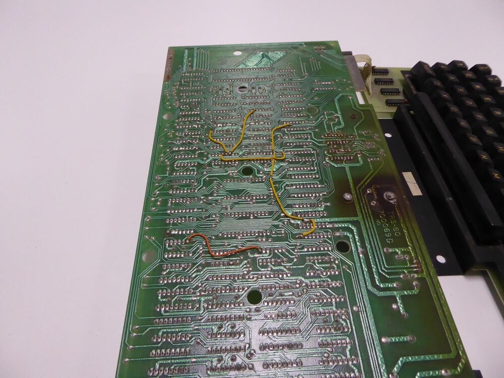
A normal TRS-80 main mother board contains 16K DRAM, and needs and "expansion interface" to add another two banks of 16K DRAM chips for the 48K RAM that BASIC 2 expects. the previous user probably did not want to buy the very expensive expansion interface and knew that it was possible to replace the uPD4116 16K x 1-bit with uPD4164 64K x 1-bit chips. I knew that this could be done because I have modified dozens of TRS-80 model 1 computers myself in the early 80's. because the uPD4116's use thre different voltages, and the more modern uPD4164's use only +5V, you have to remove some decoupling caps, and wiring .
You can see the patch wiring for this patch from the solder-side of the PCB:
One other problem many people opted to address is that the model-1 did not support lowercase letters, the designers chose a spare a few dimes by only using seven M2102 1K x 1-bit static RAM chips for video RAM. So a patch to install the missing RAM chip was quite common, and this user seems to have done the same thing. the small rectangular PCB seems to indicate this is the case.
I have not powered up the computer yet, I want to be careful, and examine the schematics first. I noticed the main +5 TO-03 Voltage regulator seems to have overheated. And I want to be sure the main regulator the MC1723 is still okay.
Re-assembled the painted TRS-80 model 1
I decided not to try to get this TRS-80 working again, the reasons are that there are two large obstacles, first I do not have the original monitor, and secondly I do not have the power supply brick. The first obstacle can be overcome,although the TRS-80 used a very special method to use a TV for a monitor, the TV they used had a "hot chassis", that is all touchable metal parts of the TV were directly connected to mains voltage, but because on a TV only the antenna input was touchable, and that was save because there was a very small (a few picofarad) high voltage capacitor in series, but that could not be the case for a monitor, so tandy used a special trick to isolate the high voltage fron the computer, in the monitor was a small pcb with a few opto isolators powered from the computer that dis the isolation. But I found out that you could get a composite video signal from the 5V DIN connector regardlessly. you can make a working vide cable by using pin 4 for video, and pin 5 for gnd, and use either a SCART, or the yellow video input of a composite monitor.
but the power is a much larger problem the TRS-80 needs both AC and DC power. pin 2 and 4 needed 19.8V DC 0.35A but also it needed AC, 17.0V AC 1A between pins 1 and 3. I do not know the polarity of the DC. So I gave up trying to power the TRS-80 Model 1, its just a showroom model. I think it is now of museum quality, see the picture below
One of the 1977 Trinity, the TRS-80 model I

