Monsteraccu
| Project Monsteraccu | |
|---|---|
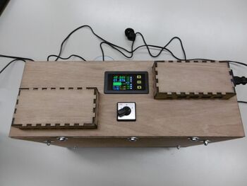
| |
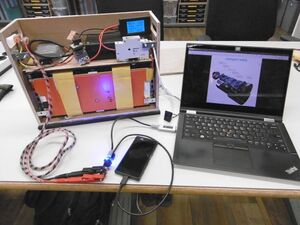
| I needed a bigger powerbank, so I built one. | |
| Status | In progress |
| Contact | Peetz0r |
| Last Update | 2022-03-26 |
WHY?!!
To charge my phone, obviously. Actually to charge 7 phones for 7 days, off the grid. As a stretch goal I also want to be able to charge my laptop and other devices using USB PD.
As a scout leader in a team of 7 we would like to be able to use our power-hungry smartphones all the time and being able to charge every night, anywhere.
I am assuming 20 Wh per phone per day. This is worst case: most phone batteries are quite a bit less, and don't get empty every day. But 7×7×20 is 980 Wh. Nearly 1 kwh.
Cells
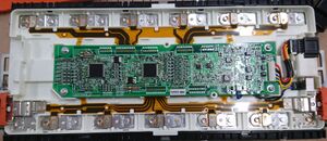
I used to work at Muxsan where we upgrade electric cars to have bigger better bad-ass batteries. The battery modules we use are around 1kwh, so it's a match! I took one from an incomplete set and started poking at it. They are 12 rectangular cells, 25 Ah, 1086 Wh, made in Japan in 2015 and it weighs in at 9,8kg. I have been told to not charge them over 4.15V. There is a BMS inside but it doesn't do much without a CAN bus to talk to. All of the protection features normally work by talking to the rest of the car which might for example switch a huge relay to disconnect the entire pack, or show scary errors on the dashboard. But the only car I own does not have a CAN bus.
Please don't ask who made them or what car they came from of where to get them yourself for how much because I will not answer that.
Charger
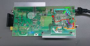
The first important part was a compatible charger. There are not many chargers that can charge 12 cells at less than 4.2V per cell, but I found one made for Bafang e-bikes that does the trick. Only at 2A though so a full charge takes ~12 hours. There is a 3A variant of this charger but it's a fair bit more expensive so I picked the 2A one.
I had to cut off the weird plug, then do some basic reversing to figure out how to turn it on. There is an ID pin over which it presumably talks to the original battery using something like onewire, then after having a nice chat enables the charger by turning on a mosfet. The actual charging (CC-CV) circuitry is always on, so when I poked around with my multimeter and found 49.2V somewhere I decided to just bridge that mosfet and call it a day. The status LED doesn't give any useful data but that's fine.
Outputs
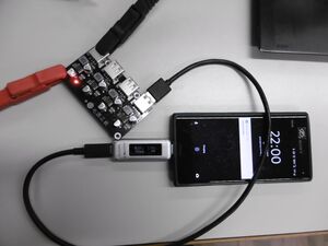
So this thing needs USB ports. Lots of them. So I went to my good old friend Ali and ordered this one. It has 4 ports on one board with mounting holes. All ports support the most common few fast charging methods. It can do from 5V 3A up to 12V 2A per port, without any funny stuff when you use multiple ports but only some can deliver full power.
But while searching I found out that must "usb power modules" have a maximum input voltage of around 30V. My battery pack has a voltage between 36V (empty) and 49.2V (full). So I decided that I needed a DC-DC converter to go in between all of this. Benadski of AltPwr helped me and had one of these RC481910 still around so I now have 19V 10A of voltage regulated power available.
For my stretch goal I wanted at least one port with USB Power Delivery, preferably supporting all the voltages (5V, 9V, 12V, 15V and 20V). I went looking on Ali and eBay and everywhere for a "USB PD source module" and did not find anything. Found many sink modules like the one in my car but nothing what I needed for this project. Until I started looking for "macbook car charger". That's technically the same thing, right? So I found the Wotobe 78W PD car charger which is basically exactly what I wanted with some extra bits around. It suypportes 12V and 24V car electrics so that's nice. I tested it with a lab supply at some different voltages below 10V and up to 30V, works fine across the whole range. Can actually deliver 60W for long periods with getting only somewhat warm. I took off the plastic and found the blue leds on the front way too bright. Took those off as well and added some wires to connect everything. Since it has no mounting holes I hotglued it in place. I used the USB A port for extra mechanical strength because I wasn't planning on actually using it.
Other parts
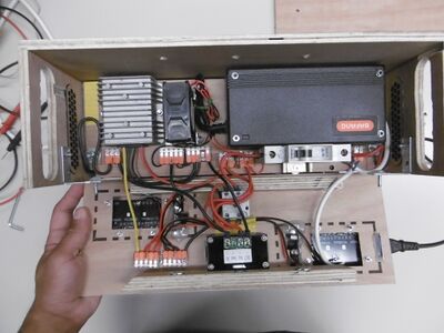
I quickly found out that charget gets rather hot, 80°C on the inside after a few minutes. So I decided that I needed a fan. Also I would like to keep moisture to a minimum and having airflow can help with that. So I decided to run the fan continuously when in use. Since this is going to be used nearby sleeping people (including myself) we now have an extra requirement for the fan: silence. So I got the most quiet 48V fan from Farnell. I was quickly disappointed, it was not very quiet at all. I think 48V fans only exist in industrial settings where nobody cares about some extra noise anyway. So I decided to look further and get a 12V Nuctua fan with moves the same amount of air but produces 19 dBA instead of 28 dBA. I quickly ordered a small DC-DC board that can run just the fan (independent of my big 19V DC-DC one).
I also would like some protection. I sawed off a small piece of dinrail and got myself an old but good condition Siemens B10 circuit breaker. This prevents against shorts but is also a nice way to turn off all the stuff inside while I am working on the 'guts of the beast'.
I also need a switch. I very much would like to be able to turn everything completely off, so I can store this for months without draining the battery. In addition I would like to prevent hooking up the charger (max 2A) directly to the outputs (could be over 3A easily with just 1 port). So I found a on-off-on switch rated for 10A DC. Switches for DC under load are typically quite bulky and expensive, but if it's just one switch it adds quite nicely to the look and feel of the box.
Then there needs to be a display to tell me when the battery is empty. Preferably with as much geeky detail as possible because why not. There is a class of panel mount displays specifically made for batteries. Some variations even come with a relay to do under voltage and other protections, and a large battery symbol on the display! I ordered this SIN9020S one.
File:Monsteraccu-SIN9020S-manual.pdf
The box
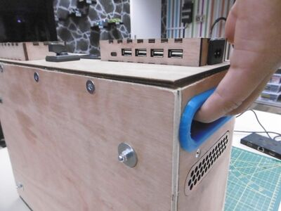
All of these parts deserve to be kept together in a nice hand-made wooden box. Thanks to many other RevSpace participants that helped me learning how to use all the workshop tools and materials! I don't think I would have made it this far without the help I got. I would have probably lasercut something that would fall apart when I'd put it together.
Most of the box is 9mm powerplex but the top part is actually lasercut from 3mm powerplex. This makes the shapes around the USB ports much easier. There is also a thick rubber sheet on the bottom and 3d-printed handle inserts.