TMC2130: Difference between revisions
Created page with " {{Project |Name=TMC2130 |Picture=Tmc2130.jpg |Omschrijving= Guide: Connecting TMC2130 and ESP8266 |Status=Completed |Contact=Sttc }} == Status == Status as of 2020/1/..." |
|||
| (5 intermediate revisions by the same user not shown) | |||
| Line 37: | Line 37: | ||
A capacitor in between Vmotor and GND is recommended (here 220µF was used) | A capacitor in between Vmotor and GND is recommended (here 220µF was used) | ||
Table: Connecting pins between TMC2130 and | [[File:Tmc2130 1.png|200px|left]] | ||
Table: Connecting pins between TMC2130, ESP8266, motor and external power supply | |||
{| class="wikitable" | {| class="wikitable" | ||
|- | |- | ||
! TMC2130 | ! TMC2130 !! ESP8266 !! Motor !! External power | ||
|- | |- | ||
| GND || GND | | GND || GND | ||
| Line 46: | Line 48: | ||
| VIO || 3V | | VIO || 3V | ||
|- | |- | ||
| OA2 || MOTOR-A2 | | OA2 || || MOTOR-A2 | ||
|- | |- | ||
| OA1 || MOTOR-A1 | | OA1 || || MOTOR-A1 | ||
|- | |- | ||
| OB1 || MOTOR-B1 | | OB1 || || MOTOR-B1 | ||
|- | |- | ||
| OB2 || MOTOR-B2 | | OB2 || || MOTOR-B2 | ||
|- | |- | ||
| GND || GND | | GND || GND || || GND | ||
|- | |- | ||
| VM || Vmotor (+8V) | | VM || || || Vmotor (+8V) | ||
|- | |- | ||
| DIR || D2 (GPIO4) | | DIR || D2 (GPIO4) | ||
| Line 62: | Line 64: | ||
| STEP || D3 (GPIO0) | | STEP || D3 (GPIO0) | ||
|- | |- | ||
| NC | | NC(not connected) || - | ||
|- | |- | ||
| | | SDO(MISO) || D6 (GPIO12) | ||
|- | |- | ||
| CSN || D8 (GPIO15) | | CSN || D8 (GPIO15) | ||
|- | |- | ||
| SCK || D5 (GPIO14) | | SCK(SPI CLOCK) || D5 (GPIO14) | ||
|- | |- | ||
| SDI || D7 (GPIO13) | | SDI(MOSI) || D7 (GPIO13) | ||
|- | |- | ||
| EN || D1 (GPIO5) | | EN || D1 (GPIO5) | ||
|} | |} | ||
== Code == | == Code == | ||
Latest revision as of 18:57, 29 February 2020
| Project TMC2130 | |
|---|---|

| |
| Guide: Connecting TMC2130 and ESP8266 | |
| Status | Completed |
| Contact | Sttc |
| Last Update | 2020-02-29 |
Status
Status as of 2020/1/15:
- Completed
Introduction
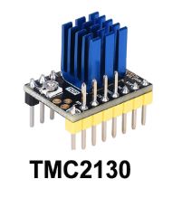
TMC2130 is utilized for driving a bi-polar step motor in this example.
TMC2130 is a driver module with many functions. This guide explains how to connect TMC2130 directly with ESP8266 via SPI without a motherboard (e.g. MKS Gen L, RAMPS, Einsy Rambo etc.).
Used components:
- TMC2130
Manufacturer: Big Tree Tech
https://www.aliexpress.com/item/32975341864.html?spm=a2g0s.9042311.0.0.5d3e4c4d6bMkco
https://www.trinamic.com/products/integrated-circuits/details/tmc2130/
https://www.dropbox.com/s/xwongsgvshapqaj/TMC2130-V2.0%20spi%20firmware.docx?spm=a2g0o.detail.1000023.19.4fc612156plDrp&dl=0
https://github.com/bigtreetech/BIGTREETECH-TMC2130-V3.0?spm=a2g0o.detail.1000023.18.4fc612156plDrp&file=BIGTREETECH-TMC2130-V3.0
- ESP8266:
LoLin NodeMCU V3 4MB flash ESP8266 12E
More info on ESP8266: https://randomnerdtutorials.com/esp8266-pinout-reference-gpios/
Wiring
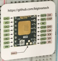
TMC2130 board must be modified for SPI communication mode according to manufacturer's instructions
A capacitor in between Vmotor and GND is recommended (here 220µF was used)

Table: Connecting pins between TMC2130, ESP8266, motor and external power supply
| TMC2130 | ESP8266 | Motor | External power |
|---|---|---|---|
| GND | GND | ||
| VIO | 3V | ||
| OA2 | MOTOR-A2 | ||
| OA1 | MOTOR-A1 | ||
| OB1 | MOTOR-B1 | ||
| OB2 | MOTOR-B2 | ||
| GND | GND | GND | |
| VM | Vmotor (+8V) | ||
| DIR | D2 (GPIO4) | ||
| STEP | D3 (GPIO0) | ||
| NC(not connected) | - | ||
| SDO(MISO) | D6 (GPIO12) | ||
| CSN | D8 (GPIO15) | ||
| SCK(SPI CLOCK) | D5 (GPIO14) | ||
| SDI(MOSI) | D7 (GPIO13) | ||
| EN | D1 (GPIO5) |
Code
Required libraries:
- TMC2130Stepper
/**
 * Author Teemu Mäntykallio
 * Modified by Sttc
 * Initializes the library and turns the motor in alternating directions.
*/
//                       ESP8266
#define EN_PIN    5  //  D1
#define DIR_PIN   4  //  D2
#define STEP_PIN  0  //  D3
#define CS_PIN    15  // D8
#define MOSI_PIN  13 //  D7
#define MISO_PIN 12 //   D6
#define SCK_PIN  14 //   D5

bool dir = true;
#include <TMC2130Stepper.h>
TMC2130Stepper driver = TMC2130Stepper(EN_PIN, DIR_PIN, STEP_PIN, CS_PIN, MOSI_PIN, MISO_PIN, SCK_PIN);

void setup() {
  Serial.begin(115200);
  while(!Serial);
  Serial.println("Start...");
  driver.begin();       // Initiate pins and registeries
  driver.rms_current(600);  // Set stepper current to 600mA. The command is the same as command TMC2130.setCurrent(600, 0.11, 0.5);
  driver.stealthChop(1);  // Enable extremely quiet stepping
  driver.microsteps(0);
  //Serial.println(driver.microsteps()); // shows microsteps setting
  digitalWrite(EN_PIN, LOW);

  //Serial.print("DRV_STATUS=0b");
  //Serial.println(driver.DRV_STATUS(), BIN);
}

void loop() {
  digitalWrite(STEP_PIN, HIGH);
  //delayMicroseconds(10);
  delay(50);
  digitalWrite(STEP_PIN, LOW);
  //delayMicroseconds(10);
  delay(50);
  uint32_t ms = millis();
  static uint32_t last_time = 0;
  if ((ms - last_time) > 3000) {
    if (dir) {
      //Serial.println("Dir -> 0");
      driver.shaft_dir(0);
    } else {
      //Serial.println("Dir -> 1");
      driver.shaft_dir(1);
    }
    dir = !dir;
    last_time = ms;
  }
}
Remarks
- ESP8266 configuration on Arduino IDE:
