SolarBatLight: Difference between revisions
Update project status |
Update project status |
||
| (3 intermediate revisions by the same user not shown) | |||
| Line 1: | Line 1: | ||
{{Project | {{Project | ||
|Name=SolarBatLight | |Name=SolarBatLight | ||
|Status= | |Status=Stalled | ||
|Contact=bertrik | |Contact=bertrik | ||
}} | }} | ||
Status: need to design a pre-amplifier and detection circuit, not entirely convinced that enough power can be supplied for a good light effect. | |||
== Introduction == | == Introduction == | ||
| Line 17: | Line 19: | ||
== Inside a garden light == | == Inside a garden light == | ||
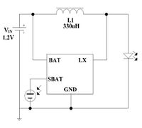
[[File:cl0116.jpg|right|200px]] | |||
A typical inexpensive (3 EUR) garden light combines the following functions: | A typical inexpensive (3 EUR) garden light combines the following functions: | ||
* detect day or night by looking at the output of the solar array | * detect day or night by looking at the output of the solar array | ||
* during the day, charge a battery (typically single cell AA NiMH) from the solar array | * during the day, charge a battery (typically single cell AA NiMH) from the solar array | ||
* during the night, step-up the voltage of the battery (about 1. | * during the night, step-up the voltage of the battery (about 1.2V) to a voltage that the LED needs (about 3V) | ||
It does this using a surprisingly simple circuit, similar to a so-called joule-thief. | It does this using a surprisingly simple circuit, similar to a so-called joule-thief. | ||
| Line 58: | Line 62: | ||
Garden light measurement results: | Garden light measurement results: | ||
* I've tried various other LEDs, the original one is pretty bright already. | |||
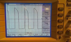
* The LED gets about 3.1V peak | * The LED gets about 3.1V peak | ||
* the step-up frequency (with the LED connected) is about 145 kHz | * the step-up frequency (with the LED connected) is about 145 kHz | ||
* the coil is charged for approximately 4.1 us, with an inductance of about 330 uH, this means about 15 mA peak through the coil. | |||
* the boost circuit appears to work in continuous mode, the 40%/60% charge/discharge times correspond nicely with the 1.2V charge and 1.8V discharge voltages. | |||
* it is estimated that on average, the LED receives half the peak coil current, or about 7.5 mA. At 3V average voltage, this means an average power of 9 mW. | |||
[[File:IMAG0525.jpg|right|300px]] | [[File:IMAG0525.jpg|right|300px]] | ||
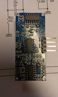
HC-SR04 measurement results: | HC-SR04 measurement results: | ||
* At the output of the final amplification stage (at pin 7 of the LM324/TL074, just before comparison with the reference level), the signal output is about 100 mV (keys rattling in front of the microphone). | * At the output of the final amplification stage (at pin 7 of the LM324/TL074, just before comparison with the reference level), the signal output is about 100 mV (keys rattling in front of the microphone). | ||
* From looking at the comparator part of the schematic, I derive that the final reference level sits at 2.41V. Compared to the average signal level of 2.5V (1/2Vcc), this means that a signal of about 88 mV amplitude causes a signal to go to the microcontroller. | * From looking at the comparator part of the schematic, I derive that the final reference level sits at 2.41V. Compared to the average signal level of 2.5V (1/2Vcc), this means that a signal of about 88 mV amplitude causes a signal to go to the microcontroller. | ||
Latest revision as of 13:01, 8 August 2014
| Project SolarBatLight | |
|---|---|
| Status | Stalled |
| Contact | bertrik |
| Last Update | 2014-08-08 |
Status: need to design a pre-amplifier and detection circuit, not entirely convinced that enough power can be supplied for a good light effect.
Introduction
This project is about combining a cheap solar-powered garden light with a simple bat detecting circuit.
The idea is that at night, as bats fly around your garden, their sonar calls are picked up by an ultrasonic microphone inside the garden light which makes it flash at the rhythm of the bat calls. Imagine an array of these lights!
Features:
- inexpensive (like EUR 5,- total)
- no need to charge the batteries (charged by sunlight)
- picks up ultrasonic audio at 40 kHz, which includes many echo-locating bats
- not very scientific but potentially mesmerizing :)
Inside a garden light

A typical inexpensive (3 EUR) garden light combines the following functions:
- detect day or night by looking at the output of the solar array
- during the day, charge a battery (typically single cell AA NiMH) from the solar array
- during the night, step-up the voltage of the battery (about 1.2V) to a voltage that the LED needs (about 3V)
It does this using a surprisingly simple circuit, similar to a so-called joule-thief. People have modded these lights before, e.g. putting different LEDs in it (more efficient, or a different color) and even putting two LEDs in series.
Ultrasonic receiver

The current idea is to re-use an HC-SR04 "pinger" module. This module can be found on ebay for about 2 EUR and consists of an ultrasonic transducer to send a few pulses at 40 kHz and another transducer to receive the echo. By determining the time between sending a pulse and receiving the echo back, the distance to an obstacle can be determined. But we're not going to actually do that!
In short, the module works like this:
- a small microcontroller on the module controls the timing of the pulse that is sent
- an RS232 level-converter boosts the pulse waveform to about +10 and -10V for a strong signal into the transmitter transducer
- on the receive side, a TL074/LM324 quad opamp is used to amplify the received echo signal
- the first three opamp stages are used to amplify, band-pass filter, amplify respectively
- the last stage compares the received signal to a reference level to determine when an echo is actually received (doing a clever trick, making it more sensitive as time goes by and no echo has been received yet)
There's a very nice analysis and schematic of the circuit at Emil's projects.
The modifications to the module will probably consist of the following:
- to save power, disable (or remove) the transmit logic, i.e. the microcontroller and the RS232 level converter
- set a fixed reference level instead of one that is variable with time
- use the existing digital output to drive a LED
Experimentation

I should find out the following things:
- How much voltage/current can the step-up circuit of the garden light deliver?
- How much current will the modded HC-SR04 circuit take?
- Will the step-up circuit interfere with the ultrasonic audio (at about 40 kHz)?
- What is the frequency of the step-up circuit (probably ultrasonic too, like 100 kHz)?
- Can the LED be made brighter?
- Does the whole thing actually work on real bats? (like pipistrellus pipistrellus or "dwergvleermuis" in the netherlands).
Garden light measurement results:
- I've tried various other LEDs, the original one is pretty bright already.
- The LED gets about 3.1V peak
- the step-up frequency (with the LED connected) is about 145 kHz
- the coil is charged for approximately 4.1 us, with an inductance of about 330 uH, this means about 15 mA peak through the coil.
- the boost circuit appears to work in continuous mode, the 40%/60% charge/discharge times correspond nicely with the 1.2V charge and 1.8V discharge voltages.
- it is estimated that on average, the LED receives half the peak coil current, or about 7.5 mA. At 3V average voltage, this means an average power of 9 mW.

HC-SR04 measurement results:
- At the output of the final amplification stage (at pin 7 of the LM324/TL074, just before comparison with the reference level), the signal output is about 100 mV (keys rattling in front of the microphone).
- From looking at the comparator part of the schematic, I derive that the final reference level sits at 2.41V. Compared to the average signal level of 2.5V (1/2Vcc), this means that a signal of about 88 mV amplitude causes a signal to go to the microcontroller.
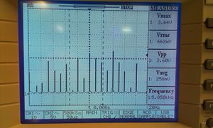
- The scope image on the right shows the signal going into the microcontroller, with the reference level at its most sensitive setting (pin 10 cut). They're rather short positive spikes, one for each time the signal crosses the reference level.
LED power
I guess we can drive the LED pretty hard because it will only be on for a small percentage of the time (e.g. typically only 5 percent or so). So, the peak current may be high, making the average current a "normal" value like 10-20 mA or so.
My idea is to charge a capacitor through a resistor and discharge it across the LED as a bat call is received. The value of the capacitor in this RC-circuit is chosen such that the energy contained in it is equivalent to 10-20 mA average when pulsed at 10 Hz, 5% duty cycle. The value of the resistor is chosen such that the C can charge fast enough between pulses at 10 Hz (so, the RC time constant is like 1/3rd the period, or about 30ms).
Silly ideas
Triangulation
- put an arduino (like the pro mini, 3 EUR) + inexpensive wireless receiver (like the NRF24L01+, 1 EUR) in each of the garden lights and make it run an ad-hoc wireless network
- run an NTP-like protocol on the wireless network to synchronize the clocks in each of the garden lights
- make each garden light report the time instant when it received a bat call, this will be different for each light because it has a different distance to the bat and the bat sonar travels at the speed of sound (about 340 m/s).
- triangulate the bat for each call it makes!