Space invaders repair
| Project Space invaders repair | |
|---|---|
| |
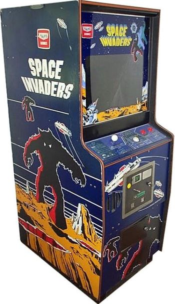
| My attempts in repairing a Space Invaders Console from 1977 | |
| Status | In progress |
| Contact | Mahjongg |
| Last Update | 2019-11-11 |
I was asked if I could repair a defective space invaders console by my friends at Awsomespace, and I said yes. This describes the vicissitudes I experienced while attempting this feat.
Note this isn't actually a RevSpace project, (as all the work is done at the Awesomespace location in Utrecht) but I still thought it was note worthy to document my experiences somewhere, as actual information is hard to come by.
The symptoms of the problem were that the console when turned on only displayed a screen full of "garbage", that is, a screen filled with a repeating pattern of seeming random pixels repeating something like eight times over the screen, with no discernible motion in this pixels.
The console had been found standing in a few inch of water in a cellar somewhere, so we feared the worst for the condition of the electronics, luckily our fears were not met by reality, as the electronics looked fine, only the very large mains transformer on the bottom of the console had been a bit wet and the woodwork has suffered.
The console came with an original document "Midway's SPACE INVADERS PARTS CATALOG" dated October 1978, "game no 739", and heavily yellowed hand drawn schematic of the main (CPU) board, and a secondary sound and I/O board. My first task was to create electronic copies from them.
after quickly verifying all the relative power supply voltages were okay, (they were) I realised that to debug these boards I had to get them on a workbench, power them independently from the consoles power supply, which wasn't really portable in any sense, so I started creating a suitable power supply from an old PC power supply. I also started looking at further documentation and soon found out that any kind of detailed description about how it all worked internally wasn't available at all, and looking at the schematics I soon found out that it was an Intel i8080 based system and was really designed very strangely, which isn't surprising as it really was the very first design incorporating a microprocessor, and video logic. It looked like something an alien being had designed, and went against all modern design concepts of an 8-bit computer system, the only thing it somewhat resembles was an old S100 bus based system, as it didn't have a bidirectional databus, but two unidirectional ones. and also incorporated what looked like data-line multiplexers. https://en.wikipedia.org/wiki/S-100_bus
I discovered some valuable documents, the main being the official repair manual, File:Midway8080testSpaceInvader.pdf.
I also discovered that the board generated a composite (monochrome) video signal, meaning I could hook it up to a test monitor.
I decided that the CPU did not run, or crashed in a loop without doing something, as the random data it was displaying (being RAM content) wasn't affected at all. After measuring that the CPU wasn't in reset state, note that pin 12 on the i8080 has to be high for the CPU to be in reset, and it was low permanently. I decided that for further testing I needed an oscilloscope (or at least a "logic probe", but these are very hard to come by these days, as they are not used anymore). Awesome space has a few very old analog oscilloscopes, one of these would do, but unfortunately there were no oscilloscope probes, so I had to wait for another repair day.
As I suspected the CPU, the intel 9316 ROM's or the 2107 RAMs (which are notoriously unreliable, as one was obviously already replaced in the past) could be defective, I needed a known good test-ROM to test them, unfortunately the system uses old intel mask ROMs (not even EEPROM's) which are also prone to get bad, but the schematic noted that 2716 EEPROMS could be used instead, and provided some very sketchy re-jumpering pictures (but note that you should NOT trust these, they are IMHO incredibly difficult to decipher, and also WRONG). Problem is that four 2716 EEPROMs these days are almost impossible to get hold of, but I did find a 27C64, which in theory could replace all four, in principle I only needed one 2716 for the (original) RAM test code, the one that would write a single digit to RAM in the middle of the screen, hoping that enough of the RAM's would be working so you could actually recognise the digit. In the end benadski found a much more involved test ROM, which did much more than that, but used all four 2K regions four 2716's), and we programmed this into the 2764 taking care to write the first of the four test roms (test.h) in the lowest of the four locations in the ROM, and test.g test.f and test.e in the succeeding ones, so as to create one blok of 8K code. Initially I thought that benadski had used the old 2K test and I did not understand why he had written four files to the ROM, but once I saw a screenshot of the testrom in action I realised what I had.
So I attempted to re-jumper the several wire links on the board for 2716's, but this failed miserably as the instructions seemed incomplete and simply wrong. In the end I simply disconnected all jumpers and used my noggin to find out how to connect the right signals to the 24-pin (EEP)ROM sockets, in the process I discovered that the roms didn't use any Output Enable Signals, only chip selects (if you used multiple (EEP)ROMS, it seems the ROM bus didn't care if any of the ROM's were addressed (in a restricted address space) and simply always were driven with data from one of the ROM's. It seems the databus multiplexers did the address allocation. Seems old intel ROM's were not designed for tri-state bus systems.
meanwhile I had discovered that the space invaders system had a simple watch dog reset system, consisting of a counter that counted 60 Hz pulses (from the video divider chain) so that unless it was regularly reset it would time out after 256/60 is roughly every four seconds, but the watch dog wasn't running because the power supply reset signal kept it in reset, once I supplied the power supply reset signal, by tying an inverter input low, (a wire over the input capacitor on the board) the watchdog was starting and the i8080 was reset every four seconds, which was what the doctor ordered, because the previously "dead cpu" (no activity on any of its address lines) suddenly came to life, nothing visible happened though, but with the .h rome removed I finally got to see the "good vertical lines" picture, that seems to indicate that RAM is working, as there were no interruptions in the lines, indicating bad RAM bits.
Still the EEPROM did not work, and in the meantime I discovered that I had an 8K testrom not a 2K testrom, so I had satisfied the EEPROM by adding address lines A11 and A12, While measuring all the pins of the EEPROM one by one (which previously had given me the insight that the "2716 jumping scheme" was completely wrong as the right signals did not end up on the right EEPROM pins, and one address pin even had 12V on it :-( , so I completely rewired the jumpering) I found out that pin 20 (Output enable) wasn't used at all! all the pin 20 pins of all eight sockets were connected together, but NOTHING was driving the /OE pin! So I wired it to A14, meaning the EEPROM would output actual data if any one of the first four roms were addressed, but tying it simply low would have worked also I think.
I was rewarded with a changed picture, instead of the "good vertical lines" picture I got a picture of either all even or all odd pixel rows being shown, alternating once every second or so. I still have no clue what this means, perhaps the documentation of the new testrom has something to say, or otherwise I have to use a logic analyser to see if the i8080 got the right EEPROM data, fortunately we seem to have just such a logic analyser at Awesome space, and old one, but it seems to work, although no one has used it yet. my latest idea as to what might be wrong, is that one of the data-bus multiplexers is bad, or it could be that the line pattern points to something specific, explained in test rom documentation. interestingly this video of a space invaders console booting this same testrom shows the exact same vertical lines I get, but then continues with other (RAM testing) patterns, this might mean that part of the boot rom is executed, but then crashes. https://www.youtube.com/watch?v=jLM_LJ-QgdE
May 5, 2017 ITS ALIVE!
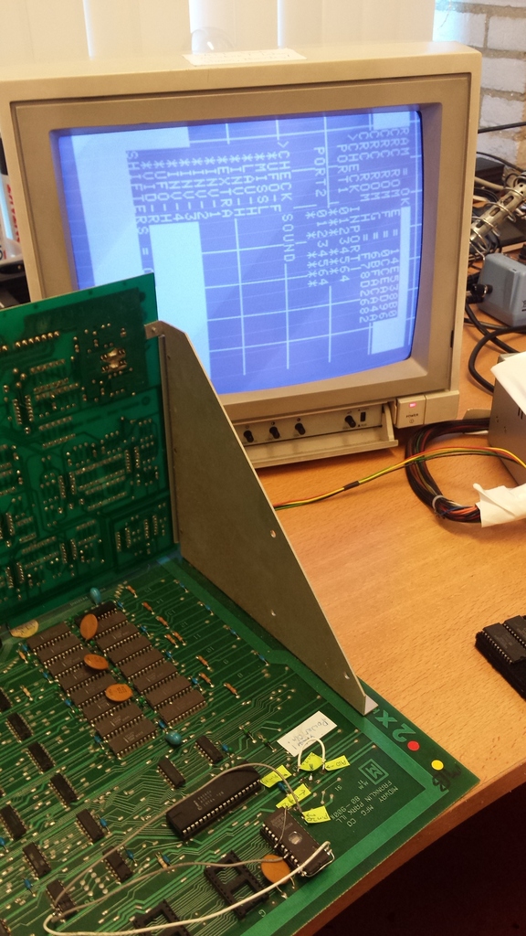
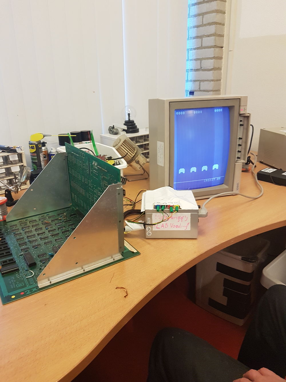
Yes, there is live in the old thing! I managed to get the testprogram working! initially it was bit of touch and go, sometimes (about one in forty attempts) it started, but most of the time I only got vertical lines, but after long a work on it, I managed to get the program to start consistently, with a press on a reset button I added, and with power-on-reset tied low with a 470 Ohm resistor. here is the proof:
This means that the culprit was that one or more of the original ROM's has developed a defect!
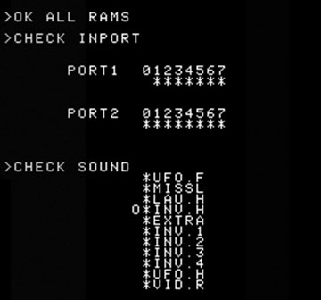
I'm not sure why the testprogram isn't displayed on an all black (in this case blue) background, but in any case its not random. Surely its not a coincidence that the background is laid out as a grid, (for easy adjustment of the monitor, obviously) but I don't know why it has two white rectangles in it either, but its very consistent, and doesn't seem to be the result of crashed code. The test program starts with a RAM test, and displays that RAM is okay, then displays the checksums of each 2K ROM (which are all programmed in the one 8K EEPROM), don't know why the four checksums are different, as I thought that three 2K ROM's didn't contain any code, at least the whole test also runs when I tie the two extra address lines permanently low, in which case all four checksums are the same, but the test runs just the same, to me that means it runs in only 2K. After calculating and displaying the checksums and the input ports, it enables all sounds in sequence one by one, doing that twice, then it displays the text "shifters = okay", and if you wait a bit longer the testscreen is replaced with a screen displaying eight columns of eight rows of two digit (I presume hexadecimal) numbers, all 64 displaying as "00". I learned that a Space invaders console, primitive as it is has hardware to shift the position of the invaders left or right, without having to move them in memory with the CPU, a kind of "blitter" or "hardware scrolling" avant le lettre.
If I connect the leftmost two switch input pins together, while the program is running the sound check, I see the two stars of port1 and port2 bit 4 disappear as long as I connect the pins together.
so we are making progress.
p.s. I found that the background we see is normal for this test ROM, this youtube move show the exact same test program we use in action, and it does exactly the same as ours, only afterwards it displays stripes, instead of the "hexdump", and it seems to restart. https://www.youtube.com/watch?v=J0KvcoGKL-4
perhaps we have a slightly newer version.
now where did I put my bottle of anti woodworm liquid, I used when the big decorative bamboo hand fan I brought with me from Indonesia had woodworm, I can use it again, as the Space invaders cabinet was diagnosed to have woordworm too. For the hand fan It worked great, just find the holes, and put a bit of liquid on each hole to kill all of them. Hope I can find that small white bottle. (no I think I threw it away)...
If anyone still has a 2764 or 27C64 EPROM, (or a 27(c)128 EPROM) then benadski can program the Space Invaders code in it, and we can try if that works too.
P.S. after some thought I found out we can instead buy an OTP (One Time Programmable) which is simply an EPROM die (chip) packaged in a package without the expensive quartz window, these still exist (32K and upwards) and are quite cheap (less than €1.50 in fact). In this case I would suggest an AT27C256R-70PU. Which can be bought from Farnell, code #1095781 Its logical that UV erasable EPROM's are obsolete as for code development you can simply use an electrically erasable EEPROM, and what made EPROM so expensive was simply the packaging with a quartz window.
I'm planning to drill 4 holes in the board, (for the four extra pins of a DIP-28 socket) so I can modify/replace the EPROM socket, so that it directly accepts 27(C)64 EPROM's, and I can clean up the wiring, which is now a bit messy.
Sunday May 14, 2017 Finished it, it works!
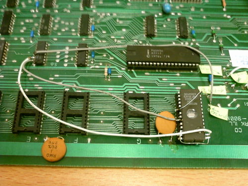
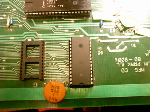
Benadsky bought a reel of 27C256 OTP ROMs and programmed one for me. I took it to awesome space. There I replaced the temporary wiring for a modified 27C64 EEPROM with a neat 32 pin socket. With the help of a Dremel I drilled four holes, and extended the 28 Pin socket to a 32 Pin socket, and wired it on the back for the 27C256 OTP.
Pictures before and after the cleanup:
I was quite confident it would work, and it did, it came alive on the workbench immediately.
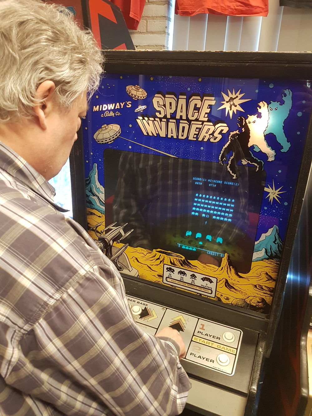
Then it was just a matter of placing it back into the console, wire it up and try it out, it worked! This is me playing a round of space invaders.
As you can see, it works. Sound is a bit soft, which probably is just the volume potmeter turned down.
Thanks to J4sp3rr for taking these last two pictures, and uploading them to Awesome Retro's Slack pages.
Afterwards I treated myself to a, (well earned I think) chicken dinner at a famous Belgian beer restaurant in the center of Utrecht, if you look well you can see at which restaurant I am.
More work on it is needed, as sound isn't completely working
Sound levels are very low, and some sounds (explosions for example) seem to be absent, also the "thumping" sound that is so typical is absent. This means I have to take it out, and on the bench once more, after first trying the test ROM inside the cabinet, as on the bench the test ROM didn't seem to produce any sounds, and it even didn't seem to enable the output ports to enable any of the sound generating circuits.
Found out that the low level the symptom point to a defective LM3900 quad norton amplifier, just before the 2 Watt speaker driver (LM377). LM3900's are probably impossible to procure so I have to find a substitute. luckily it seems only half of the particular LM3900 is used, I'm planning to remove the IC, and replace it with a socket, in which I will place a module with a dual opamp, a regular amplifier (not a norton one) but with rail to rail inputs and being able to be powered by 12V single or dual supply (schematic is unclear about LM3900 power pins , so I need to look at the actual PCB, but I expect a +12V only supply is used, not a +12V -12V supply). When sound starts working I can check which one or more sound effects are missing, and repair them where needed.
Around July 2017 I managed to replace almost all LM3900's which brought back many sounds
I had not expected it, but it seems that LM3900 are still made, probably because no modern replacement of this norton amplifier exists, and it seems people are still designing with it, or there is a sufficiently large market for replacement chips. After first successfully replacing the speaker amplifier driver LM3900, I decide to buy ten more LM3900 and 14-pin DIP sockets, and I replaced all LM3900's except one, which I initially overlooked, with them. This brought back many sounds, but not all of them. I can still replace the lone remaining old LM3900, as several of them must have died, but I do not expect that one to bring the thumping sound back, AND the explosions. My current idea is that the system has a broken pseudo random (noise) generator, but it seems that its using CMOS parts you can no longer get... At least I will replace the one remaining LM3900, and do some measurements on the pseudo random generator if droning and explosions are not brought back by the LM3900.
23 september 2017 replaced the last LM3900
Yeah, I replaced the one remaining LM3900 with a new one, and also replaced the one CD4016 analog switch chip that was in the system with a more modern replacement the CD4066. It made no discernible difference. I added GND and +5V points to connect a test probe, and looked at the noise generator, but I found no noise, as the noise output was always low. Also the oscillator for the digital noise generators clock signal was always low, so I suspect the CD4030 XOR ports chip to be defective, and not generating a clock signal for the 4006 shift register. Perhaps i can still find a CD4030, finding a CD4006 ( a long chain of shift registers ) will be far more difficult to find, and it might not be broken. P..s in hindsight I should have powered the probe with 12V, not 5V as I did, as now its results might not be reliable, but yes a 12V high would certainly be seen as a high, so I guess it doesn't matter. So I still I expect the CD4030 to be defective, at least its certainly the pseudo random noise generator that is not working, as its the reason why explosions (sort bursts of noise) do not work, and why player firing sounds strange, as both use the noise from the random generator. Ill try to find a CD4030, or a replacement.
26 September, 2017 found a replacement for the CD4030
I found a quad XOR pin-compatible with the CD4030, in the form of a CD4070, and I got one. The only difference between the 4030 and the 4070 is that the latter has a different input ESD protection, and the 4030 was made obsolete very early on (you can still buy some, but you have to buy more than one, and they are more expensive than a CD4070). Hope to try the CD4070 soon, and hopefully the pseudo random (noise) generator will then work. That is, if the CD4006 is not defective as well, if it is it will be almost impossible to source a replacement, and I will have to build one from scratch using multiple other IC's.
2 October, 2017 a new CD4070 did not revive the pseudo random generator
So I replaced the CD4030 by a CD4070 in a socket and tried the Space invaders console. The result was a screen filled with random dots! also after turning it on and off a few times, it seemed that the digital electronics were broken again. That was a very big disappointment, and I uttered a few disappointed words...... Tried cleaning the contacts of the various connectors, and pressing chips in their sockets, and tried again, it wasn't working I was just voicing my disappointment (back to the drawing board, ugh..) to a few bystanders when suddenly the console started working again, I suspect the power on-reset circuit in the power supply also has a broken capacitor or something like that. I remember that a member of awesome space had said something like that, but I had not experienced the problem before. Anyway, I quickly tried if the explosion sounds were now working, but they were not! :-(
Some probing with my digital probe brought to light that yes, the CD4006 was now getting a clock signal, but no it was not generating a pseudo random data-stream. Conclusion, the CD4006 is also dead. Luckily Benadsky has come to my rescue once again, as he has located a source of CD4006 IC's for €0.75, so for a few euro we hopefully can get one. (I heard one is coming from India, of all places). this will be continued. Although it is taking a long time for the CD4006 to arrive, I hope it will still come....
Drawn the schematic of the pseudo noise generator
It takes a very long time for the CD4006 to arrive from India, and I'm starting to believe it won't come.
I have done some research and believe its possible to re-create the CD4006 using some other IC's, such as the CD4015, and CD4517, which are still available. So I drew up a schematic of the pseudo noise generator, with the details of what logic is in the CD4006, in order to be able to study it.
here is a .PDF of it:
File:Space invaders pseudo ruis generator.pdf
and here is a picture of the .PDF:
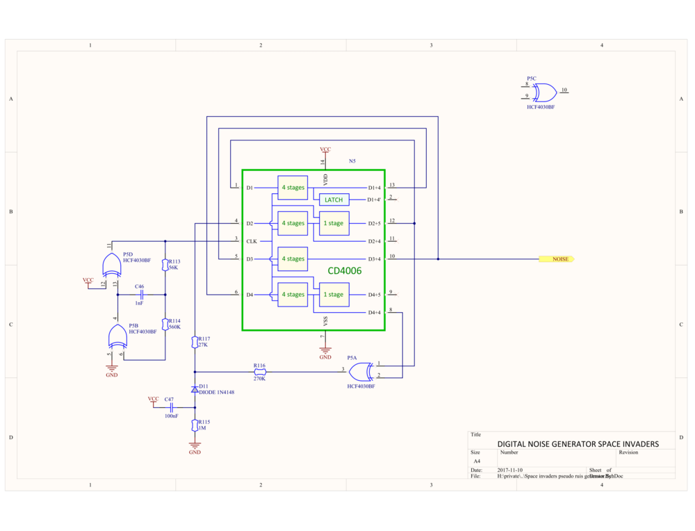
The circuits uses a chain of 4 + 5 + 4 + 4 = 17 shift registers, one stage isn't used, as isn't the latch.
If we (arbitrarily) take pin 10 as the logical end of the shift register chain, then if we work back we see 4 + 4 = 8 stages before a node occurs with a branch to an XOR, then going further back we see 5 stages before we get to the "input" (D2) consisting of a "initialisation & XOR output" circuit. This circuit produces either a duration of "logic highs" during power on, or after that the output of the XOR. So we can see that initially the shift register chain is filled with "1"'s, to initialise it to a know state, and later it is filled with the result of the XOR.
The end of the chain (pin-10, the noise output) goes on to another 4 stages, before reaching the other XOR input. Its this XOR which produces the pseudo random stream of 1's and 0's from the two input signals.
The other two XOR's are used as an inverter and a buffer, which form an oscillator which generates the clock for the shift registers.
This is the simplified schematic diagram:

However I learned that the CD4006 will arrive soon, so I don't need to design the replacement circuit.
In the end the CD4006 did indeed arrive, and the random generator worked, and brought explosion sounds back, but it seems there is still something missing, namely the “droning” sound
In the mean time it has become more and more difficult to get the console out of reset, it often takes many attempts before it will start, the suspect is the power good reset circuit on the power supply board, but all attempts to fix the supply have failed to make a difference,and now the CRT seems to develop problems, resulting in a distorted and rolling picture.
Don’t know how to fix that, besides exchanging all the capacitors in the CRT logic pcb.
11/11/2019 Done a course on CRT repair, and now know how to fix the CRT
The arcade cabinet repair course I did from Randy Fromm has given me some knowledge, and I now know how to fix the monitor. Also I have build a component tester that can use to test the ESR (equivalent series resistance) of an electrolytic capacitor to check if it has dried out (one of the most important failure modes that happen in arcade cabinets that are several decades old.
