RadarOnAStick
| Project RadarOnAStick | |
|---|---|

| |
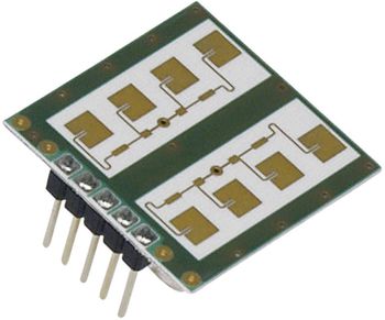
| A doppler radar sensor connected to a PSOC5 DevKit, outputting the IQ-signals over USB stereo audio | |
| Status | Abandoned |
| Contact | bertrik |
| Last Update | 2022-07-28 |
"Everything is better on-a-stick!"
Status
2016-02-14 Created this page, just writing down the basics
Concept
The goal of this project is to create an easy-to-use integrated doppler-radar-module that outputs the complex radar signals over USB stereo audio. The left and right channels represent the I and Q components of the complex radar signal respectively, ready for further processing, e.g. complex FFT to separate the positive and negative frequencies.
The basic idea is to take a relatively inexpensive bistatic doppler radar sensor and connect it to a PSOC5 development kit:
- the doppler radar sensor is this RSM2650 doppler sensor, also known as Innosent IPS-265 (datasheet). It works at 24 GHz and outputs low-frequency I and Q signals. Having both the I and Q components allows you to sense not just *speed* of movement but also *direction* of movement.
- this PSOC5 development kit which can be bought for about E10,- at Farnell. This PSOC5 development-kit combines a powerful Cortex-M3 processor with several programmable analog blocks, like analog amplifiers , opamps, and analog-digital converters. The kit already comes with some example code for implementing USB devices.
The plan is for the doppler radar sensor to be connected with as little as possible "glue electronics" to the PSOC dev-kit, using the analog capabilities of the PSOC5 for thing like amplification, offset-compensation, etc. I want to use the GnuRadio framework to process and visualize the complex radar signal. GnuRadio is already capable of using USB-audio like devices as a signal input, for example the FUNcube dongle and generic audio sources.
A possible application of such an integrated sensor-module is to sense the movement of bats as they fly in and out of their roost of hibernation place. In this application, the radar-on-a-stick could be put into the USB-port of a small Linux board (like a Raspberry Pi), which takes care of recording the signal, high-level processing like classification and communication with the outside world.
Radar basics
The Doppler radar module outputs a sine/cosine-like signal when something in its field of view moves.
The frequency of the output signal is related to the velocity of the movement: roughly f = v * (2 * F / c), where:
- f = output frequency
- v = velocity of movement (actually the velocity of the distance change w.r.t. the sensor)
- F = radar carrier frequency, approximately 24x10^9 Hz
- c = light speed, approximately 3x10^8 m/s
So movement of 1 m/s gives an output signal of about 160 Hz, for this specific radar sensor.
Another way to look at this is to consider that if the TOTAL reflected distance (forth AND back) between the sensor and object changes by one wavelength (12.5 mm), you get one complete sine/cosine "cycle" out of the radar sensor. This means you need only half a wavelength distance change (6.25 mm) per cycle. Also, when moving faster, you get more cycles per second.
The amplitude of the Doppler signal depends on various things:
- how well the material of the moving object reflects radio signals at the radar frequency
- the size of the moving object (and to some extent the geometry of the object)
- the distance between the radar and the object, this is quite a dramatic 4th power relation: twice the distance means a reduction by 16 times of radar power received back
This particular radar sensor outputs a quadrature signal, basically you get a sine and a cosine-like wave from the I and Q outputs, with a relatively large static offset. The mutual phase between these signals allows you to tell if an object is moving toward or away from the sensor. In a complex frequency spectrum this appears as either a positive or negative frequency.