EspWifiTracker
| Project EspWifiTracker | |
|---|---|
| Location-tracker based on WiFi station ids | |
| Status | Stalled |
| Contact | bertrik |
| Last Update | 2024-12-01 |
Status
News:
- 2016-07-13 Published some ugly Java code for the server side of this project, see https://github.com/bertrik/wifitrackerserver
- 2016-06-12 Measured power consumption of an alternative ESP8266 board, the Wemos D1, it does indeed draw a lot less power in sleep mode than the NodeMCU (about 0.16 mA, should last about 180 days on a 700 mAh battery)
- 2016-06-12 Figured out how the DS3231 RTC alarm works: the RTC alarm sets an internal alarm flag and makes the RTC SQW pin low, however the SQW pin stays low until the alarm is cleared in software.
- 2016-04-25 Measured power consumption of the NodeMCU board. The consumption in deep-sleep is a rather disappointing 3.3 mA (expected something < 1 mA). I might need to go to a different ESP8266 platform than the NodeMCU.
- 2016-04-19 Connected a LiFePO4 battery and made a scan of the trip from RevSpace to Gouda, one point every 20 seconds. Using this kind of battery to power the ESP8266 directly seems to work fine!
- 2016-04-10 Made my first actual scan and processed the data using the Google location service. I'm using pin D5 to decide between "run mode" (scan, log, sleep) and "debug mode" (accept commands from the serial port)
- 2016-03-26 I've been thinking about using the WiFiManager component, this component presents you with a web page to configure stuff, like the name/password of the AP to connect to the internet. It also allows you to configure extra properties. I could put the URL of the upload server in these extra properties (and just HTTP GET the rest of the settings from the server).
- 2016-03-25 I got submission of wifi scan results to google working, Mozilla appears to use a compatible format (i.e. the google JSON format with some extensions).
- 2016-03-17 Can't really get the wake-up using the DS3231 to work, the interrupt pin appears to be active all the time, keeping the ESP in reset. I think I'll just use the ESP built-in wake-up mechanism.
- 2016-03-16 Working on a prototype using a NodeMCU with a DS3231 RTC
Next steps:
- Make some nice Java service to accept the JSON data, store/convert the data to coordinates and host it somewhere
- create a kind of blacklist/whitelist mechanism that scores each scanned AP for suitability to connect to the internet, based on AP name / security type / whether we know the password / etc. A negative score could mean that it should definitely NOT try to connect using a specific AP. The AP with the highest score is tried first
Open challenges:
- make it smaller and lighter: so it can be attached to smaller items (e.g. a migrating bat)
Decisions:
- Forget about trying to access the web using unsecured access points. Open access points are highly likely to be run with a captive portal, which are non-trivial to bypass automatically.
Introduction
The idea of this project is to create a simple and low-cost WiFi location tracker.
It tracks location by periodically scanning for WiFi station ids, storing those in internal memory and using one of the various location services (google, mozilla, openwlanmap, etc.) to determine a geographical location from this.
This can be used to track various things, for example:
- track your own bicycle
- know where your cat goes
- monitor movement of wild animals for research purposes, like bats or stone martens.
The basic operating principle is this:
- the tracker is in deep-sleep most of the time, keeping only a low-power real-time-clock running.
- every once in a while (say once a day) it wakes up, takes a reading of all WiFi stations in range and their signal strength. It stores these in internal memory.
- if the tracker wakes up to find an WiFi station that it can use to access the internet, it tries to upload all previous readings to a server.
- the server resolves the uploaded data into geographical locations using a service like Google or the Mozilla Location Service.
Tracker prototype
Hardware
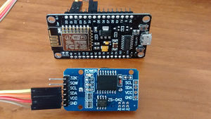
I'm basing this on an Wemos D1 mini. This board is basically an ESP8266-module on a break-out board with an USB-serial converter and a proper 3.3V power supply. The ESP8266 is a WiFi-capable microcontroller, capable of running at 80 MHz, most versions commonly sold have 4 MB of flash onboard with enough spare flash sectors to hold a file system.
Pin D0 (GPIO16/WAKEn) is connected to RST to support wake-up-by-reset with the ESP internal deep sleep mode.
To keep time, I'm using a ZS-042 clock module, containing a Maxim DS3231 RTC chip (datasheet). This module is attached to the NodeMCU through the I2C-bus on pins D1 (GPIO5/SCL) and D2 (GPIO4/SDA). I removed the power LED on board the ZS-042 module, since one of my reasons for using an RTC is to save current by keeping the electronics mostly in low-power sleep mode and the power LED wastes current unnecessarily.
Pin D5 (GPIO14) is used to distinguish between run mode and debug mode during reset/wake-up. When this pin is pulled low (e.g. by a wire to GND), the tracker goes into debug mode. If this pin is left floating, an internal pull-up makes it high and the tracker goes into run mode.
I'm powering the ESP8266 directly off a single cell LiFePO4 battery. In particular I'm using a "14500" battery, which has the same dimensions as a common "AA"/"penlite" battery. A single cell of this type outputs about 3.2-3.4V, which is a good match for the ESP8266 voltage requirement of 3.3V.
Possibly the high power consumption during sleep mode can be fixed like discussed here.
Wake up from sleep
Basically I know of two practical mechanisms to save power by going into deep sleep and waking up again:
- Connect pin D0 (GPIO16/WAKEn) to the RST pin and use the ESP.deepSleep(x) command. This puts the ESP into a low-power deep sleep mode for x microseconds. After these x microseconds, pin D0 pulses low causing a reset of the entire ESP8266. I think this can keep the ESP in sleep mode for a maximum time of about 1h11m35s (2**32 microseconds).
- Put the ESP to sleep using the ESP.deepSleep(0) command and use an external RTC to generate a reset pulse on a specific wake-up time. The DS3231 RTC can generate an alarm signal on an arbitrary date and time, but it outputs a level-like signal (low if the alarm has triggered). You cannot tie this signal to the ESP reset pin because it would keep the ESP in reset indefinitely. The trick is to connect a capacitor (about 1 microfarad) between the RTC alarm output and the ESP reset input. The capacitor turns the low-going edge into a negative pulse, causing only a short reset pulse after which the ESP can clear the alarm in the RTC.
Software
The ESP board can be conveniently programmed from the "Arduino" development environment using the Arduino core for ESP8266 WiFi chip
This already comes with a library for WiFi that allows you to scan for WiFi stations
Other libraries used:
- Makuna RTC (by "Makuna" - Michael Miller) which can be installed into the Arduino environment by going to menu Sketch/Include Library/Manage libraries..., then searching for 'Makuna rtc' and installing it.
My prototype software can be found at: https://github.com/bertrik/wifitracker
modes
The software can run in one of two modes, run mode and debug mode.
If pin D5 is pulled low during start-up, the software goes into debug mode In debug mode, it runs a simple command interpreter, type 'help' at 115200 bps to get a list of supported commands.
If pin D5 is left unconnected, the software goes into run mode. In run mode, the device scans APs, saves the result to a time-stamped file in flash memory and goes back to sleep as soon as possible to save power.
AP selection
TODO: check out https://wiki.bitlair.nl/Pages/Projects/KPN_Hotspots_Autologin and see if I can run it inside an ESP.
I'm thinking of a kind of whitelist/blacklist mechanism to select an AP for uploading data. The plan is to score each scanned AP against this list and then select the one with the highest score, excluding APs which have a negative score. The first match in the list determines the score, so the list is ordered from most specific to least specific. The score is based on network name and encryption type.
This way, we could select and AP on a preference order, for example:
- first, try a secure network that we know the password of;
- next, try an open network that we know is open to the internet (probably very rare...);
- ignore any open network that we know is not really open or uses a captive portal (like "KPN Fon")
- try any open network that is unknown to us.
For example, the entries in the list could look like this:
- {score=100, ssid="my_home_network", pass="my_home_pass"}
- {score=100, ssid="my_work_network", pass="my_work_pass"}
- {score=-100, ssid="KPN Fon", pass=""}
- {score=-100, ssid="WiFi in de trein", pass=""}
- {score=-100, ssid="McDonalds FREE WIFI", pass=""}
- {score=0, ssid="*", pass=""}
where an entry with an empty password represents an open network.
main program flow
The ESP wakes from sleep on reset:
- read the RTC to determine if it's time to do a scan, else go to sleep again
- scan wifi networks
- append the results of the scan to file, the file name is based on the current date.
- score each network for suitability for upload, if none is found, go to sleep again
- connect to the network and probe for actual internet connectivity
- upload the log files one by one, delete the file if successful
- download new settings files
- try to perform an NTP sync and update the RTC if successful
- go to sleep.
data structures
The plan is to use JSON for data to be uploaded. The log file is also formatted as JSON, so during upload we can simply upload the log file without further processing. The advantage is that JSON is readable to humans, disadvantage is that it needs more space than a binary format. The log file contains one line per wifi scan, example of JSON:
{"deviceid":"18FE34XXXXXX","datetime":"2016-03-21 12:34:56","scan":[{"mac":"123456787878","rssi":-49},{"mac":"785634121212","rssi":-42}]}
The device id is the ESP MAC address. Times are in UTC.
The Google Location Service seems to be interested in the channel too (not sure why), we could also log this.
For the settings file, I'm thinking of a simple ini/properties file structure, with KEY=VALUE pairs in it, with empty lines and lines starting with "#" being ignored.
Server backend
Initial code for the server code receiving uploads from the trackers: https://github.com/bertrik/wifitrackerserver
The server backend receives uploads from the tracker and resolves the WiFi station ids into locations by using a location service, for example:
- Google maps geolocation API
- Mozilla Location Service
- OpenWLANmap.org
- see also this WiFi positioning page on Wikipedia.
The MAC address of the ESP8266 should be unique and can be used to identify a specific tracker.
Communication between the tracker and the server is always initiated by the tracker. The protocol is REST (HTTP) and the format is JSON. I'm thinking of writing this in Java, with the use of Jackson 2.0 (JSON), Jersey 2.0 (REST) and Jetty libraries.
The REST service could have two endpoints:
- one to upload collected WiFi data from the tracker to the server
- one to download configuration data from the server to the tracker
Configuration data can be made specific for each tracker, and could consist of things like:
- a new periodic wake-up schedule
- list of known WiFi stations + passwords
- WiFi station whitelist, list of stations which are known to be really open to the internet
- WiFi station blacklist, list of stations which are open (unencrypted), but not really open to the internet
Results
NodeMCU Power consumption
I've measured the current drawn by an NodeMCU board from the battery under different circumstances.
Results:
- while scanning for APs: not sure, it draws a short high peak, my multi-meter registered a maximum value of about 150 mA.
- in "idle" mode, running the command interpreter: 80 mA
- in deep sleep mode: 3.9 mA
The NodeMCU deep sleep mode current is a very disappointing, I was expecting a lot lower. Just this current will drain a 700 mAh battery in about a week. Disconnecting the RTC gives a current of 3.3 mA, so most of the deep sleep current appears to be consumed somewhere on the nodemcu board.
Wemos D1 mini power consumption
This board seems to draw about 0.16 mA in deep sleep mode. Draining a 700 mAh battery would take about 180 days, quite acceptable.
2016-04-23
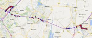
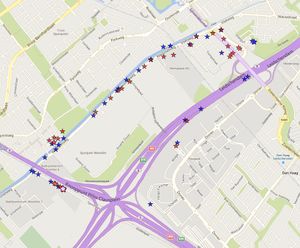
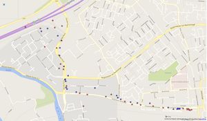
Shown here is a plot of locations from an AP scan done every 10 seconds, while traveling by car from RevSpace (The Hague area) to the train station of Gouda. Locations have been resolved using both the Google geo-location API (blue) and the Mozilla Location Service (red). In total, Google was able to resolve 220 locations, Mozilla was able to resolve 204 locations.
You can see clearly that both Google and Mozilla give a lot of fixes in urban areas. We probably drove with a speed of around 50 km/h in the urban areas (and stopping for some traffic lights) and around 130 km/h on the highway. Noticeable is a huge gap on the A12 highway north of the town of Zevenhuizen, for both Google and Mozilla.