Bringing up Rhococo (first boot, and firmware development)
| Project Bringing up Rhococo | |
|---|---|

| |
| This tells the story of how the firmware and software was developed that gives rhococo its functionality | |
| Status | In progress |
| Contact | mahjongg |
| Last Update | 2019-07-22 |
This page describes the initial bringing up (designing and installing firmware and software) that will give Rhococo its functionality.
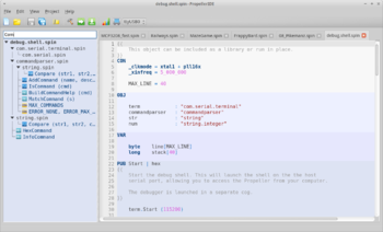
First we have to install the tools we need. For programming the propeller we have to install the propeller IDE, https://developer.parallax.com/propelleride/ . Fortunately I have already installed the latest version, when doing some initial research, and I have it working with my propeller based game development system, I bought some ten years ago, when thinking about building my own home computer was still a pipe dream.
May 1, 2019 First attempts at sending a propeller program to Rhococo
I tried to send a modified version of LEDblink to Rhococo but failed (my debug LED is on A0, just like the Hydra). I was not sure my USB-serial adapter was compatible, and I used an oscilloscope to check, but that wasn't it, the adapter, which is intended for small Arduino compatibles without a built in serial programming port, seemed okay, and DTR was toggled by the programming software. Only for some unclear reason the nRESET input on the propeller stayed low. The USB dongle had a 100nF cap in its DTR line, but that could not be it. I removed the 2N3904 transistor, but nRESET kept being stuck low. All the schematics I could find about the programming interface seemed to imply that the nRESET pin had a built in pullup, so I hadn't implement an external one, but it seemed that without one nRESET didn't go high. So I added a 10K pullup, and now nRESET goes high, but without a new 2N3904 I have to wait till next week to try again.
May 2, 2019 Found out why nReset "floats"
its because I have tied the brownout input (BOEn) high, this turns off the built in 5K pullup. BOEn should be tied low instead.
May 3, 2019 updated schematic and Layout
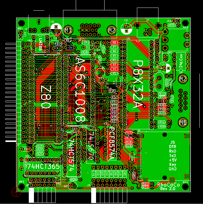
new version is revision 2.0 (after version 1.9) it has BOEn tied low, and other recent updates, such as bleeder resistors, an 5mm pitch caps. schematic is here: File:RHOCOCO rev2.0.pdf
May 4, 2019 programming the propeller works ITS ALIVE!
I managed to get BlinkLEDRhococo.spin to upload, and program into the Rhococos EEPROM, and the blinking program starts when turning on the USB supply.
May 22, 2019 trying to get a standard VGA driver (32 x 16 text driver) to work
I'm trying to convert VGA.SPIN so that it works with RhoCoCo. It works on a Hydra game development system, but Hydra isn't hardware compatible with rhococo, so I have to change a few things. I managed to make it work with a 5MHz crystal, instead of the Hydra's 10MHz crystal, but Rhococo also has its VGA hardware on a different set of pins, namely gpio-0 to gpio-7, while Hydra seems to have in on gpio-16 to gpio-23 (hydra documentation is vague). These are the three .SPIN files, each using a COG that demonstrate the VGA text mode driver already modified for a 5MHz xtal: File:Vga text demo spin.pdf, File:Vga text spin.pdf, File:Vga spin.pdf
I'm also figuring out the version of the propeller IDE for Linux, which isn't the same as the Windows version described in the Hydra documentation.
The progress is painfully slow, but I am convinced that i'm close to success.
This will just be a placeholder VGA driver, so I have a textmode display for my Z80 uploading debug work.
May 28, 2019 VGA driver works!
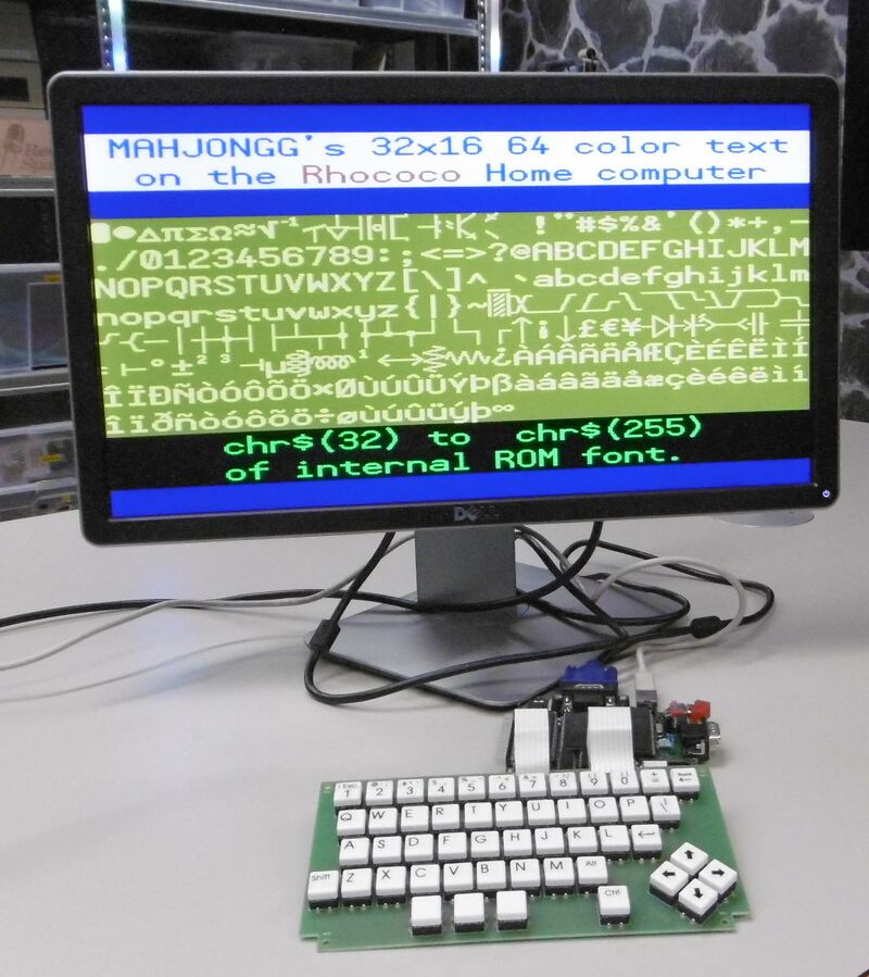
Here is a picture of the VGA monitor displaying a picture directly produced by the RhoCoCo.
No hardware modifications were necessary, and Rhococo is clocked with a 5MHz crystal.
With this video terminal it will be much easier to develop firmware such as the Z80 RAM upload code, and IORQ handlers.
June 5, 2019 Thinking about video modes
This TV driver is text only, but I'm thinking about some modifications that will turn it into a high-resolution graphics driver.
one idea is using two sets of 256 programmable fonts, and assigning one glyph of the font per character position.
The text screen (horizontal x vertical number of glyphs) for this (VGA Text) driver is by nature 32 x 16, so you can display 32 x 16 = 512 glyphs on one screen. so if you had two font-sets of 256 glyphs you could have one glyph for every position on the screen. The propeller chip itself has a massive high resolution 16K ROM containing 256 character definitions of a 16 pixels wide by 32 pixels tall characters. 16 pixels = 2 bytes X 32 x 256 = 16484 or 16K. The Propeller has 32K hub RAM, meaning that theoretically you could store other such font sets in hub RAM, but that leaves no hub RAM at all left over, so storing two such fonts is not a useful proposal, and also having a 32K video framebuffer in Z80 RAM isn't practical either.
Still this method of generating high resolution screens has some practical advantages, so I don want to give up on the idea immediately.
VGA Text claims to have a practical horizontal screen resolution of 16 x 32 = 512 pixels and a vertical resolution of 32 x 16, also 512 lines. So it seems the actual resolution generated is 512 x 512.
However a VGA monitor I connected claims the actual VGA resolution of the generated video signal is 640 x 480 @ 60Hz, so it seems the vertical resolution is cropped, and indeed I only count 15 lines of text, not 16. 480 / 32 = 15.
And 640 - 512 = 128 pixels, probably 64 pixels left and 64 pixels right of the visible area are "black".
so the generated resolution is 640 x 480 and the "pixels resolution" is (or seems to be) 512 x 480.
perhaps with 15 lines instead of 16 its possible to store enough glyphs in hub RAM with some RAM space left over. In theory we need 2 byte x 32 x 32 = 2048 or 2K per line, so 15 x 2K or 30K (30720 bytes), leaving only 2K left over.
What I would prefer is using something like a spectrum with 8x8 glyphs, and a 256 x 192 pixel resolution, and a on a 32 x 24 tile screen. 768 glyphs would be needed, so it fits in a ten bit number, 8 bits + two more bits.
It is clear this needs more study, especially I need to study the VGA TILE drivers, and see how they work.
perhaps its better to let this be, and first concentrate on loading up and running some Z80 code.
June 11, 2019 IO-Expander (for SD-Card IO) working
To upload some Z80 code to RAM I need an easy to change data source, so any kind of SD-card I/O, or reading files directly from the serial EEPROM, or Z80 code embedded in the propeller code. Because I want to implement some kind of SD-card interface anyway, and because the SD-card interface works through an PCF8574A IO expander, I decided to try to get the I/O expander working. That meant I needed I2C driver code, and code to manipulate the PCF8574A. the PCF8574A is a very early, and simple I/O expander. There is no "data direction register", and you can only write or read all 8-IO-bits. The output must be written high to be able to read the I/O pin as an input, but all pins are pulled up anyway so that isn't much of a problem. to be able to change single pins the solution is to use a mirror byte, and manipulate the bits in the mirror byte before writing it out. Reading a single bit means reading all bits, and masking the required bit out.
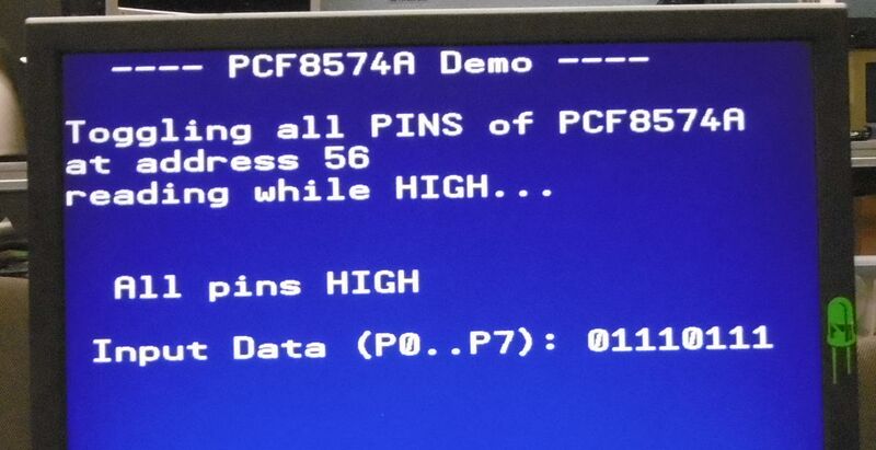
I managed to modify simple code I found online written for the even older PCF8574 for the PCF8574A, and as the picture shown below shows, it works.
you can see that P0 and P4 are pulled low, by the card_detect, and write-protect switch respectively, with all other I/O's being inactive (high).
next, implementing a simple SD-card interfacing software, this will be a very simple FAT16 driver, without subdirectories, and with 8.3 filename conventions, later I can write a better driver, but for now such a driver will suffice. I found a 2GB SD card, (needed so the card can be FAT16 formatted, instead of FAT32) formatted it as FAT16 and placed a single text file test.txt on it for testing.
June 11, 2019 solved sd-card insertion crashes
I noticed that more often than not, the system crashed the moment I inserted an SD-card in the slot. I determined that this generated a inrush-current power dip, which the brownout detector saw as a reason for resetting the system. I solved the problem by increasing the local 3V3 decoupling capacitor C13 from 100nF to a 6.3mm 470uF 6V3 elco.
I have updated the schematic and PCB layout, to revision 2.1. File:RHOCOCO rev2.1.pdf
July 22, 2019 Need to lean Propeller assembler to proceed
Although I have I2C communication with the I/O expander working, using the propellers built in higher language interpreter (SPIN) the longer I think about writing a SD-card driver the more I'm starting to be convinced that relaying on SPIN is a bad idea, if I want to be frugal with my cogs. So I need to re-write the I2C driver in assembler, and also the SD-card code. That is a big step for me, so it will take some time to master this.
additionally I wrestling with a request to release my ZX81+35 design. In principle I feel its not yet ready, as I have a problem generating a stable video signal when running in turbo mode (220% faster). Probably due to switching the clock speed at the wrong moment(s), but on the other hand I really don't want to spend much more time to fix it. In normal mode the design works fine, and you can get a 10% speed increase by switching just one of the two turbo mode switches. So I want to release the latest PCB designs as-is. Problem is HOW? Can't release them here, this site does not support distributing .ZIP files. So perhaps I need to learn to use github...?


