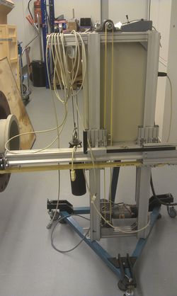
CNC plasma cutter
| Project CNC plasma cutter | |
|---|---|
| Status | Initializing |
| Contact | [[Project Contact::Walter, Smeding, Gori, Yotson, Semafoor]] |
| Last Update | 2014-04-09 |
After acquiring a plasma cutter at the space, it seemed only logical to try and fabricate a CNC version eventually.
This goal is still a while away for now, but as always, we are full of Ideas and this is a convenient place to put them.
CNC plasma cutter based on VSL X-Z table

The working mechanics
Once upon a time, three consecutive interns at VSL made a X-Z traversing unit to automatically measure wind speed velocity distribution of one of VSL's primary standars. This traversing unit was put out of use over half a decade ago, and was finally put on the scrap metal list. If it wasn't for a hackers intervention, it would have been there by now. Luckily it can now have a second life in the spark shack.
The X-Z traversing units has a DC motor for each direction of travel. These motors are coupled to a gearbox and a rotary encoder. A toothed belt then transfers the rotational motion into a linear motion.
Hardware that works

- The motors move the X and Z axis when operated by the joystick controller.
- The X and Z directions have smooth movement over an approximate 1 x 1 m range
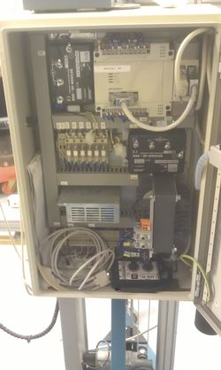
- Speed is adjustable by means of knobs inside the contol cabinet.
- The two motorcontollers work [[1]]
Hardware that needs to be sorted
- The onboard RS-232 PLC (Mitsubishi something or other) may or may not work. If it still works, we need a way to program it. Possibly it's easiest to take out the PLC and put an Arduino or Rpi in there instead
- Interface with the plasma cutter (relay, some cable and a plug to match the plug that's already on there)
- mounting for the plasma cutter head
- some rig to reliably hold the sheets of steel vertical (very important for thin sheets that may bulge or buckle otherwise)
- a PC that will survive the Spark Shack
Software that needs to be sorted
- Program for the hardware controller
- Motion control
- Speed control
- Plasma cutter on/off
- position feedback
- ...
- CNC software to draw/cut
- Perhaps use the software from the laser cutter?
Original Ideas
Specs
- 3x3 m working area
- movement speed of 1000mm/s
- Calibrated accuracy and precision of +/- 0.1mm
Axis motors
smeding is going to design and build a proof of concept linear (synchronous) motor for use in the X- and Y-axes. This test rig will be used to determine whether a DIY LSM is at all useful for our application and to finalize the design if we choose to go with the concept. Specifically, this involves figuring out:
- How the attainable accuracy compares to the wanted specifications
- How the attainable movement speed compares to the wanted specifications
- A final design for the drive electronics
- Coil and armature geometries
- Rail geometries (magnet size, spacing and orientation pattern and any backing)
- Optimal control schemes
After this, we'll be ready to construct the three rails (2x X and 1x Y) that make up the bulk of the CNC machine.
prototype BOM
- angle extrusion, probably aluminium for the prototype
- skate bearings (we already have some)
- magnets
- copper wire (we already have some)
- electronics:
- Microcontroller ([[2]]?)
- MOSFET drivers (half-bridge or BLDC)
- MOSFETs (N-channel, high current)
Some rough ideas by Yotson
- 1.5 x 3.0 Meter max. material size. Spec of plasma cutter mentions 12mm as max thickness.
Table should manage to hold the weight of a 1.5m x 3.0m x 20?mm sheet of steel.
- weight of plasma nozzle + hoses/wires?
- length of nozzle + hoses/wires?
- speed of nozzle over material > 10 cm per second. (non cutting)
- nozzle placement accuracy: < 1mm
- transportable. Able to fit through 'standard' door (on its side, obviously)
- Maybe:
'upgradeable' by placing rotary cutting tool, pencil, knife, spray can, .... ???
Transport axes: x, y: angle iron and skate wheels + bearings?
linear motors?
threaded rod, DC motors, encoders?
z : ? + threaded bolt, manual adjustment between height of 0mm and 50mm.
Threaded rod info
ISO standard. From HTTP://en.wikipedia.org/wiki/ISO_metric_screw_thread
| Diameter in mm. | Pitch (fine) | Pitch (coarse) | Rotational speed 10 cm/s lin. motion (coarse) | Rotational speed 10 cm/s lin. motion (fine) |
|---|---|---|---|---|
| 20 or 22 | 2.5 | 1.5 or | 40rps, 2400rpm | 50rps, 3000rpm |
| 2 | 66.7rps, 4000rpm | |||
| 30 or 33 | 3.5 | 2 | 28.6rps, 1714rpm | 66.7rps, 4000rpm |