CO2MeterHacking
| Project CO2MeterHacking | |
|---|---|
| Status | Initializing |
| Contact | bertrik |
| Last Update | 2014-03-19 |
Introduction
This project is about hacking the Voltcraft CO-100 CO2-sensor, such that we can read the exact ppm value as displayed on the LCD.
This particular CO2-sensor is present in the klusbunker at RevSpace and is currently used to control the ventilation in a crude manner (by monitoring the warning LEDs on the display module). Having the CO2 ppm value available as a number allows for nice things such as logging the levels over time, announce them on IRC, show them on the LedBanner , etc.
The user manual of the Voltcraft CO-100 says "Attention! The RJ45 connection (see chapter 7, item „K“) must not be used. The connection is only intended for the manufacturer". Of course, a claim like that can only be interpreted as a challenge! :)
Investigation

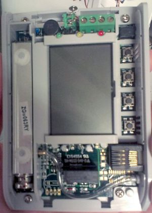
The CO2 sensor inside the CO-100 (in the left of the picture) has a sticker saying ZGw063RY. Googling for this number reveals a CO2 module that looks just like the Voltcraft CO-100, so it appears that the CO-100 is basically just a rebranded ZyAura ZGw063RY module.
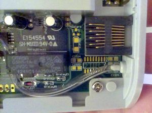
The CO-100 seems to miss a bunch of components that can be mounted on the PCB, close to the RJ45 connection (possibly an RS232 chip with step-up capacitors).

CO2 sensor
The CO2 sensor in the CO-100 looks very much like the ZyAura ZG-01 module. The ZG-01 sensor uses the SPI protocol, see the File:ZyAura CO2 Monitor Carbon Dioxide ZG01 Module english manual-1.pdf.
Other sensors on the market:
- Telaire T6613/T6615
- Winsensor MH-Z14, looks nearly identical to the Telaire module
Future work
Possible further investigation:
- Sniff the ZG01 SPI connection, e.g. using a bus pirate, Arduino or a Raspberry pi
- figure out if the CO2 sensor SPI message uses HEX or BCD format
- Check if the pads in the lower-left of the PCB say "G C D V", that could be the Ground, Clock, Data, Vcc lines from/to the ZG-01 sensor, just like in the user manual document.
- Check if the empty footprint on the PCB matches a max232
Idea
A practical solution could be as follows:
- Wire the Vcc, Gnd, Data, Clock lines of the ZG-01 to the unused pads around the RJ45 connector, such that these signals become available on the RJ45 connector;
- Attach an arduino (pro mini) through a cable on the RJ45. The arduino takes power from the RJ45 and decodes the SPI-like signals from the ZG-01.
- Connect an NRF24L01+ module to the arduino SPI port and send the CO2/temperature frames over the air to a central NRF24L01+ receiver (e.g. the one which handles the SkipButton, Nomz Bell).
- From there on, the CO2/temperature data can be further processed (to be logged, sent to the ledbanner, announced on IRC, etc.)
This requires only minimal modifications to the CO-100 modules itself and makes uses of the existing wireless infrastructure.