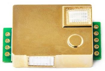
MH-Z19B
| Project MH-Z19B | |
|---|---|
| |
| Some research into the MH-Z19B CO2 sensor | |
| Status | Completed |
| Contact | Disasm |
| Last Update | 2019-10-01 |
Introduction
MH-Z19B is an updated version of the MH-Z19 sensor.
Datasheet: https://www.winsen-sensor.com/d/files/infrared-gas-sensor/mh-z19b-co2-ver1_0.pdf
Hardware
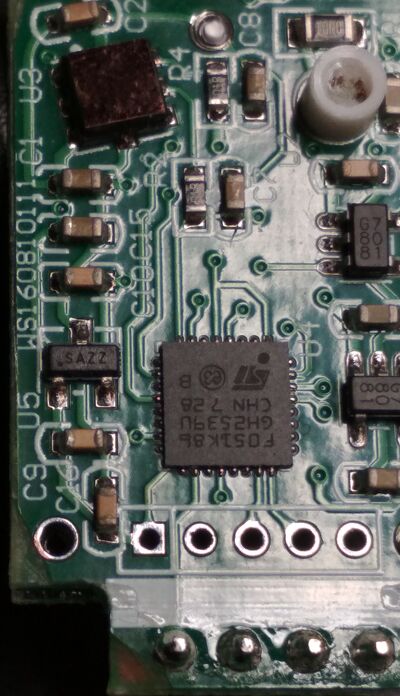
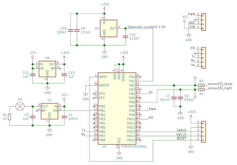
- STM32F051K86 MCU
- Unknown analog light+temperature sensor
- Two 3.3V regulators
- 1.5V voltage reference
- Lamp
Teardown
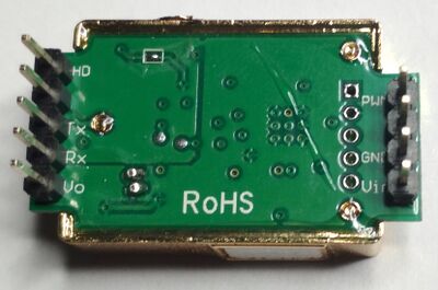
Back side of the MH-Z19B sensor with unlabeled SWD pads on the right:
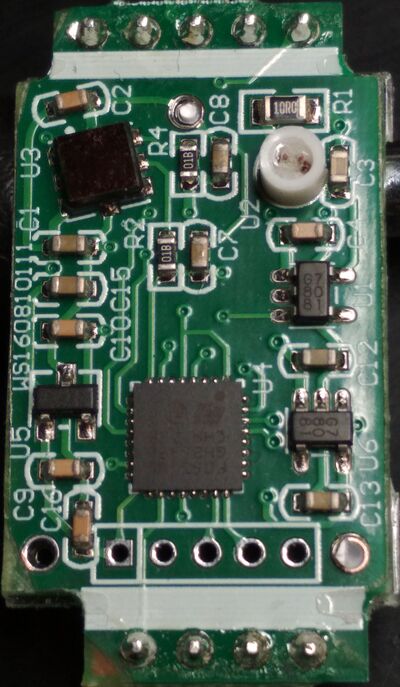
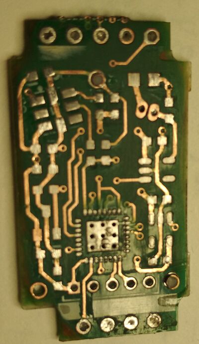
Front side of the (4-layer) PCB:
Partial schematics:
Firmware
MCU firmware can be easily dumped through SWD pads. Pinout:
| Pin | Signal |
|---|---|
| 1 (square) | 3V3 |
| 2 | GND |
| 3 | SWDIO |
| 4 | SWCLK |
| 5 | RESET (active low) |
Additionally, bootloader asks for a firmware update during the first 20s of startup.
Operation
Firmware turns on lamp for 400 ms and measures sensor response along with the voltage of the voltage reference. This happens again and again in cycle. Default cycle length is 5s.
Firmware measures only a part of the response signal: 180..980 ms interval in 10ms steps. It integrates 180..680 ms interval and removes constant component (1.026V on the image above) based on values from the 930..980 ms interval. Obtained result after some smoothing is available (divided by 2) via command 0x84. This value is used for subsequent computations.
Another firmware turns on lamp for 500 ms and measures 450..500 ms and 1800..1850 ms intervals, then uses the second one to remove constant component from the first one.
As stated in the datasheet, MH-Z19B should be kept away from heat. Experiment showed that the light sensor inside MH-Z19B stops working when MH-Z19B is exposed to an air stream from a heat gun.
Interface
Sensor provides UART, PWM and analog output interfaces. Both PWM and analog output provide CO2 measurement result limited by some bounds. UART interface implements one of several protocols. Default protocol ("operation mode 0") is the richest one.
Protocol (operation mode 0)
All commands and responses are 9 bytes in size. Most of the commands have a response, but some -- don't. Response contains command code, both command and response contain checksum value.
Command format: 0xFF, 0x01, CMD, (5 bytes of parameters), CKSUM
Response format: 0xFF, CMD, (6 bytes of response), CKSUM
For short, hereinafter this response will be called "ACK": 0xFF, CMD, 0x01, 0x00, 0x00, 0x00, 0x00, 0x00, CKSUM
In the following table in Request and Response fields only the meaningful bytes will be shown. For example, b[3] is the first parameter byte and b[3..4] is the first two parameter bytes forming a word. "???" means "isn't investigated yet", an empty field means "no parameters".
| Command | Request | Response | Description |
|---|---|---|---|
| 0x78 | b[3] | no response | Changes operation mode and performs MCU reset |
| 0x79 | b[3] | ACK | Turns ABC logic on or off (b[3] == 0xA0 - on, 0x00 - off) |
| 0x7D | r[7] | Returns ABC logic status (1 - enabled, 0 - disabled) | |
| 0x7E | b[3], b[4..5] | r[2..3] | Sets timer cycle length (b[4..5]) in seconds and returns current value. b[3] should be 2 to update the length |
| 0x80..0x83 | b[3], b[4..7] | no response | Writes one double word to the 1024-byte configuration area (offset = b[3] + (CMD - 0x80) * 256).
Command 0x80 with b[3]==0 clears the whole configuration area. On timeout this configuration area will be written to flash. |
| 0x84 | r[2..3], r[4..5], r[6..7] | Returns "raw" values. r[2..3] is a half of the raw light sensor value. r[4..5] is constant 32000.
r[6..7] is different in different versions of firmware: bit field or maximum light ADC value | |
| 0x85 | r[2..3], r[4..5], r[6..7] | Returns "raw" values. b[2..3] is smoothed temperature ADC value. b[4..5] is CO2 level before clamping.
b[6..7] is minimum light ADC value | |
| 0x86 | r[2..3], r[4], r[5], r[6], r[7] | r[2..3] - "final" CO2 level. r[4] - (temperature in C) + 40
r[6] and r[7] - if ABC turned on - counter in "ticks" within a calibration cycle and the number of performed calibration cycles. | |
| 0x87 | b[5], b[6], b[7] | r[2], r[3..6] | ??? |
| 0x88 | b[3..4] | r[2..3]=b[3..4] | ??? |
| 0x8D | no response | MCU reset | |
| 0x90..0x93 | b[3] | r[2..5] | Reads a double word from configuration area by offset (b[3] + (CMD - 0x90) * 256) |
| 0x94 | b[3], b[4..6] | r[2..6] | Changes 3 bytes (b[4..6]) of "id string" with offset (3*(b[3] - 1)) |
| 0x95 | b[3] | r[2], r[3], r[4..6] | Reads 3 bytes of "id string" (b[4..6]) with offset |
| 0x99 | b[4..7] | ACK | Sets sensor range. Note that parameter bytes differ from those in the datasheet. |
| 0x9A | b[4] | ACK | ??? |
| 0x9B | r[2..5], r[6], r[7] | Returns sensor range (r[2..5]) | |
| 0x9C | r[2..5], r[6]=1 | ??? | |
| 0x9F | b[3] | ACK | ??? |
| 0xA0 | r[2..5] | Firmware version string? "0430" and "0443" observed | |
| 0xA1 | b[3] | ACK | ??? |
| 0xA2 | b[3] | r[2], r[3..6] | ??? |
| 0xA3 | r[2..3] | ??? | |
| 0xA4 | b[3..4], b[5..6] | r[2] | Setting bounds for DAC output, r[2]==1 on success |
| 0xA5 | r[2..3], r[4..5] | Reading bounds for DAC output | |
| 0xAA | b[3], b[4] | r[2], r[3] | ??? |
| 0xAB | b[3], b[4] | r[2], r[3] | ??? |
| 0xAC | b[3] | r[2], r[3..6] | ??? |
