CO2MeterHacking
| Project CO2MeterHacking | |
|---|---|
| Status | Initializing |
| Contact | bertrik |
| Last Update | 2014-03-23 |
Introduction
This project is about hacking the Voltcraft CO-100 CO2-sensor, such that we can read the exact ppm value as displayed on the LCD.
This particular CO2-sensor is present in the klusbunker at RevSpace and is currently used to control the ventilation in a crude manner (by monitoring the warning LEDs on the display module). Having the CO2 ppm value available as a number allows for nice things such as logging the levels over time, announce them on IRC, show them on the LedBanner , etc.
The user manual of the Voltcraft CO-100 says "Attention! The RJ45 connection (see chapter 7, item „K“) must not be used. The connection is only intended for the manufacturer". Of course, a claim like that can only be interpreted as a challenge! :)
Investigation

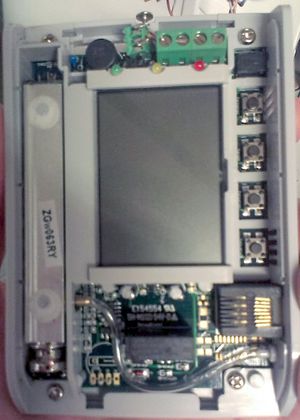
The CO2 sensor inside the CO-100 (in the left of the picture) has a sticker saying ZGw063RY. Googling for this number reveals a CO2 module that looks just like the Voltcraft CO-100, so it appears that the CO-100 is basically just a rebranded ZyAura ZGw063RY module.
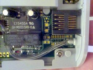
The CO-100 seems to miss a bunch of components that can be mounted on the PCB, close to the RJ45 connection (most likely an RS232 chip with charge pump capacitors).

CO2 sensor
The CO2 sensor in the CO-100 looks very much like the ZyAura ZG-01 module. The ZG-01 sensor uses the ZyAura protocol, which vaguely resembles SPI, see File:ZyAura CO2 Monitor Carbon Dioxide ZG01 Module english manual-1.pdf.
Other sensors on the market:
- Telaire T6613/T6615
- Winsensor MH-Z14, looks nearly identical to the Telaire module
Software
Some software has been written (so far untested) to interface an arduino to the clock and data lines of the ZG-01. It consists of an finite state machine (FSM) that processes the data line on each falling edge of the clock line. The FSM assumes that a new frame is starting when the time between bits is more than 3 milliseconds.
Arduino pin mapping:
- digital pin 2 (PD2): ZG01 clock signal
- digital pin 3 (PD3): ZG01 data signal
The source code can be found on github.
Future work
Possible further investigation:
- Sniff the ZG01 SPI connection, e.g. using a bus pirate, Arduino or a Raspberry pi
- figure out if the CO2 sensor SPI message uses HEX or BCD format
- Check if the pads in the lower-left of the PCB say "G C D V", that could be the Ground, Clock, Data, Vcc lines from/to the ZG-01 sensor, just like in the user manual document.
Idea
A practical solution could be as follows:
- Wire the Vcc, Gnd, Data, Clock lines of the ZG-01 to the unused pads around the RJ45 connector, such that these signals become available on the RJ45 connector;
- Attach an arduino (pro mini) through a cable on the RJ45. The arduino takes power from the RJ45 and decodes the SPI-like signals from the ZG-01.
- Connect an NRF24L01+ module to the arduino SPI port and send the CO2/temperature frames over the air to a central NRF24L01+ receiver (e.g. the one which handles the SkipButton, Nomz Bell).
- From there on, the CO2/temperature data can be further processed (to be logged, sent to the ledbanner, announced on IRC, etc.)
This requires only minimal modifications to the CO-100 modules itself and makes uses of the existing wireless infrastructure.