CO2MeterHacking: Difference between revisions
mNo edit summary |
No edit summary |
||
| Line 13: | Line 13: | ||
The user manual of the Voltcraft CO-100 says "Attention! The RJ45 connection (see chapter 7, item „K“) must not be used. The connection is only intended for the manufacturer". Of course, a claim like that can only be interpreted as a challenge! :) | The user manual of the Voltcraft CO-100 says "Attention! The RJ45 connection (see chapter 7, item „K“) must not be used. The connection is only intended for the manufacturer". Of course, a claim like that can only be interpreted as a challenge! :) | ||
== Investigation == | == Investigation & findings == | ||
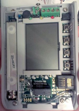
[[File:Co-100_overview.jpg|thumb|right|CO-100 internals]] | [[File:Co-100_overview.jpg|thumb|right|CO-100 internals]] | ||
The CO2 sensor inside the CO-100 (in the left of the picture) has a sticker saying ZGw063RY. | The CO2 sensor inside the CO-100 (in the left of the picture) has a sticker saying ZGw063RY. | ||
| Line 21: | Line 21: | ||
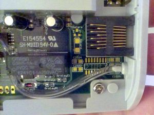
[[File:Co-100.jpg|thumb|left|components around the RJ45 connector]] | [[File:Co-100.jpg|thumb|left|components around the RJ45 connector]] | ||
The CO2 sensor in the CO-100 is a [http://www.zyaura.com/products/ZG_module.asp ZyAura ZG-01 module]. | |||
The CO2 sensor in the CO-100 | This sensor uses the ZyAura protocol, which vaguely resembles SPI, see [[File:ZyAura_CO2_Monitor_Carbon_Dioxide_ZG01_Module_english_manual-1.pdf|ZG01 CO2 Monitor Module user manual]]. | ||
On the bottom left of the PCB is a set of pads that are marked with G, C, D, V, meaning Ground, Clock, Data, Voltage of the ZG01 sensor. | |||
The voltage level on these pins is 3.3V. | |||
* | |||
The ZG-01 sends 5-byte frames containing measurement values: | |||
* byte 0 is an identifier for the measurement item, e.g. whether it is a CO2 ppm value or a temperature. | |||
* byte 1 and 2 contain the value of the item (byte 1 is the MSB, byte 2 is the LSB) | |||
* byte 2 is a checksum over bytes 0-2, just the sum modulo 256. | |||
* byte 3 is always 0x0D | |||
Besides the CO2 ppm value and temperature, it also sends various other (so far unknown) measurement items. | |||
[tabel hier] | |||
== Software == | == Software == | ||
Software has been written to interface an arduino to the clock and data lines of the ZG-01. | |||
It consists of an finite state machine (FSM) that processes the data line on each falling edge of the clock line. | It consists of an finite state machine (FSM) that processes the data line on each falling edge of the clock line. | ||
The FSM assumes that a new frame is starting when the time between bits is more than 3 milliseconds. | The FSM assumes that a new frame is starting when the time between bits is more than 3 milliseconds. | ||
Measurements of the CO2 ppm level are sent over the air using a 2.4 GHz NRF24L01+ module. | |||
Arduino pin mapping: | Arduino pin mapping: | ||
* digital pin 2 (PD2): ZG01 clock signal | * digital pin 2 (PD2): ZG01 clock signal | ||
* digital pin 3 (PD3): ZG01 data signal | * digital pin 3 (PD3): ZG01 data signal | ||
* TODO: pin mapping of the NRF24L01+ module. | |||
The source code can be found [https://github.com/bertrik/co2sensor on github]. | The source code can be found [https://github.com/bertrik/co2sensor on github]. | ||
== | == Integration == | ||
The plan to integrate the CO2 sensor into the space infrastructure is as follows: | |||
* Attach an arduino to the G, C, D, V lines. The arduino takes power from the V-line and decodes the SPI-like signals from the ZG-01 on the C-line and D-line. | |||
* Connect an NRF24L01+ module to the arduino SPI port and send the CO2/temperature frames over the air to a central NRF24L01+ receiver (e.g. the one which handles the SkipButton, Nomz Bell). The unique 4-character id for the CO2 sensor is "CO_2". | |||
* | |||
* Connect an NRF24L01+ module to the arduino SPI port and send the CO2/temperature frames over the air to a central NRF24L01+ receiver (e.g. the one which handles the SkipButton, Nomz Bell). | |||
* From there on, the CO2/temperature data can be further processed (to be logged, sent to the ledbanner, announced on IRC, etc.) | * From there on, the CO2/temperature data can be further processed (to be logged, sent to the ledbanner, announced on IRC, etc.) | ||
This requires only minimal modifications to the CO-100 modules itself and makes uses of the existing wireless infrastructure. | This requires only minimal modifications to the CO-100 modules itself and makes uses of the existing wireless infrastructure. | ||
== Future work == | |||
Future investigation: | |||
* consider powering the Arduino from the 3.3V line coming from the CO2 sensor | |||
* fix the wireless RF24 based protocol, it seems to work sometimes, but not all the time | |||
* investigate further into the unknown measurement items sent by the ZG01 | |||
Revision as of 13:40, 25 March 2014
| Project CO2MeterHacking | |
|---|---|
| Status | Initializing |
| Contact | bertrik |
| Last Update | 2014-03-25 |
Introduction
This project is about hacking the Voltcraft CO-100 CO2-sensor, such that we can read the exact ppm value as displayed on the LCD.
This particular CO2-sensor is present in the klusbunker at RevSpace and is currently used to control the ventilation in a crude manner (by monitoring the warning LEDs on the display module). Having the CO2 ppm value available as a number allows for nice things such as logging the levels over time, announce them on IRC, show them on the LedBanner , etc.
The user manual of the Voltcraft CO-100 says "Attention! The RJ45 connection (see chapter 7, item „K“) must not be used. The connection is only intended for the manufacturer". Of course, a claim like that can only be interpreted as a challenge! :)
Investigation & findings

The CO2 sensor inside the CO-100 (in the left of the picture) has a sticker saying ZGw063RY. Googling for this number reveals a CO2 module that looks just like the Voltcraft CO-100, so it appears that the CO-100 is basically just a rebranded ZyAura ZGw063RY module.
The CO-100 seems to miss a bunch of components that can be mounted on the PCB, close to the RJ45 connection (most likely an RS232 chip with charge pump capacitors).

The CO2 sensor in the CO-100 is a ZyAura ZG-01 module. This sensor uses the ZyAura protocol, which vaguely resembles SPI, see File:ZyAura CO2 Monitor Carbon Dioxide ZG01 Module english manual-1.pdf.
On the bottom left of the PCB is a set of pads that are marked with G, C, D, V, meaning Ground, Clock, Data, Voltage of the ZG01 sensor. The voltage level on these pins is 3.3V.
The ZG-01 sends 5-byte frames containing measurement values:
- byte 0 is an identifier for the measurement item, e.g. whether it is a CO2 ppm value or a temperature.
- byte 1 and 2 contain the value of the item (byte 1 is the MSB, byte 2 is the LSB)
- byte 2 is a checksum over bytes 0-2, just the sum modulo 256.
- byte 3 is always 0x0D
Besides the CO2 ppm value and temperature, it also sends various other (so far unknown) measurement items. [tabel hier]
Software
Software has been written to interface an arduino to the clock and data lines of the ZG-01. It consists of an finite state machine (FSM) that processes the data line on each falling edge of the clock line. The FSM assumes that a new frame is starting when the time between bits is more than 3 milliseconds. Measurements of the CO2 ppm level are sent over the air using a 2.4 GHz NRF24L01+ module.
Arduino pin mapping:
- digital pin 2 (PD2): ZG01 clock signal
- digital pin 3 (PD3): ZG01 data signal
- TODO: pin mapping of the NRF24L01+ module.
The source code can be found on github.
Integration
The plan to integrate the CO2 sensor into the space infrastructure is as follows:
- Attach an arduino to the G, C, D, V lines. The arduino takes power from the V-line and decodes the SPI-like signals from the ZG-01 on the C-line and D-line.
- Connect an NRF24L01+ module to the arduino SPI port and send the CO2/temperature frames over the air to a central NRF24L01+ receiver (e.g. the one which handles the SkipButton, Nomz Bell). The unique 4-character id for the CO2 sensor is "CO_2".
- From there on, the CO2/temperature data can be further processed (to be logged, sent to the ledbanner, announced on IRC, etc.)
This requires only minimal modifications to the CO-100 modules itself and makes uses of the existing wireless infrastructure.
Future work
Future investigation:
- consider powering the Arduino from the 3.3V line coming from the CO2 sensor
- fix the wireless RF24 based protocol, it seems to work sometimes, but not all the time
- investigate further into the unknown measurement items sent by the ZG01