Treinonderdelen/ICMm/Bestemmingsaanduiding: Difference between revisions
From RevSpace
< Treinonderdelen | ICMm
No edit summary |
Add dump of flash chips |
||
| Line 15: | Line 15: | ||
Grotendeels gebaseerd op dezelfde hardware als het [[Treinonderdelen/SGMm/Display_extern#Hardware|SGMm-display]], maar véél beter in elkaar gezet. | Grotendeels gebaseerd op dezelfde hardware als het [[Treinonderdelen/SGMm/Display_extern#Hardware|SGMm-display]], maar véél beter in elkaar gezet. | ||
* Flash: | |||
** Atmel AT29C010A, label: "340141 V.1.01" | |||
*** Package: PLCC32 | |||
*** [https://up.shiz.me/f/NS_ICMM_ESD_340141_v1.01_AT29C010A@PLCC32.BIN Dump] | |||
** Atmel AT29C010A, label: "340142 V.1.01" | |||
*** Package: PLCC32 | |||
*** [https://up.shiz.me/f/NS_ICMM_ESD_340142_v1.01_AT29C010A@PLCC32.BIN Dump] | |||
** [https://up.shiz.me/f/NS_ICMM_ESD_340141_340142_v1.01_stitched.bin Stitched] | |||
Resolutie: 160 x 32 | Resolutie: 160 x 32 | ||
Revision as of 02:50, 5 April 2025

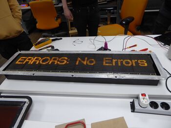
Het LED-display aan de buitenkant dat aangeeft waar de trein naartoe gaat.
- Fabrikant: Focon Electronic Systems A/S
- Onderdeelnummers:
- Nedtrain:
- YA082984
- YA08298C
- Focon:
- Label: 800313-02 ("External Side Display (ESD)")
- In software: 390024 ("Focon Electronic Systems A/S DSB dot 16")
- Nedtrain:
Hardware
Grotendeels gebaseerd op dezelfde hardware als het SGMm-display, maar véél beter in elkaar gezet.
- Flash:
Resolutie: 160 x 32
Connectors
Één Harting Han 24DD-connector aan de bovenkant van het display, met de volgende pinout:
   _/-----------\_
 _/  21  - 23  -  \_
/    17  - 19  -    \
|    13  -  -  -    |
|     9  -  -  -    |
\_    -  -  -  -   _/
  \_  1  2  -  - _/
    \-----------/

 1: power Vcc
 2: power GND
 3: N/C                             [no pin]
 4: N/C                             [no pin]
 5: N/C                             [no pin]
 6: N/C                             [no pin]
 7: N/C                             [no pin]
 8: N/C                             [no pin]
 9: address bit (0?)
10: address bit (1?)                [no pin]
11: address bit (2?)                [no pin]
12: address bit (3?)                [no pin]
13: RS-485 GND
14: RS-485 GND (for address bit 2?) [no pin?]
15: RS-485 GND (for address bit 1?) [no pin?]
16: RS-485 GND (for address bit 0?) [no pin?]
17: RS-485 in-
18: RS-485 in-                      [no pin]
19: RS-485 out-
20: (debug RX?)                     [no pin]
21: RS-485 in+
22: RS-485 in+                      [no pin]
23: RS-485 out+
24: (debug TX?)                     [no pin]
Één interne JST-connector van de hoofdconnector naar het logica-bord, niet nodig voor externe verbinding:
Pin  1: RS-485 IN+       [external: pins 21 and 22]
Pin  2: RS-485 IN-       [external: pins 17 and 18]
Pin  3: signal GND       [external: pins 13-16]
Pin  4: (debug RX?)      [external: pin 20]
Pin  5: (debug TX?)      [external: pin 24]
Pin  6: signal GND       [external: pins 13-16]
Pin  7: address bit (0?) [external: pin 12]
Pin  8: address bit (1?) [external: pin 11]
Pin  9: address bit (2?) [external: pin 10]
Pin 10: address bit (3?) [external: pin 9]