InductionHeater: Difference between revisions
No edit summary |
Start of overhaul: power stage documentation |
||
| Line 2: | Line 2: | ||
|Name=InductionHeater | |Name=InductionHeater | ||
|Status=In progress | |Status=In progress | ||
|Contact= smeding | |Contact= smeding | ||
}} | }} | ||
| Line 11: | Line 11: | ||
* [https://www.youtube.com/watch?v=l7fArOvXhQY https://www.youtube.com/watch?v=l7fArOvXhQY] | * [https://www.youtube.com/watch?v=l7fArOvXhQY https://www.youtube.com/watch?v=l7fArOvXhQY] | ||
== | ==System design== | ||
Induction heating works by applying a high-frequency magnetic field to the (conductive) workpiece being heated. Because of the [https://en.wikipedia.org/wiki/Skin_effect skin effect], conduction at these frequencies only occurs in a thin layer on the outside of the workpiece. This acts like the secondary winding of a transformer, allowing current to flow and heating the workpiece through resistive heating. | |||
The design consists of the following parts: | |||
The | * The power stage rectifies mains voltage, which is then chopped into a high-frequency 'modified square wave' with variable duty cycle and frequency. | ||
* The coupling transformer transforms the relatively high-voltage, low-current square wave into a lower-voltage, high-current one, to ease the requirements on the work coil. | |||
* The work coil is where the workpiece is placed to be heated. | |||
* The controller monitors relevant currents and voltages, and generates the waveforms that drive the power stage transistors. | |||
===Specs=== | |||
* Input power: Standard single-phase mains: 230V RMS, 16A max ⇒ 3.5kVA | |||
* Frequency: 10 kHz - 100 kHz | |||
* 500A absolute maximum current in work coil | |||
* 'Modified square wave' control: variable frequency and duty cycle | |||
==Power stage== | |||
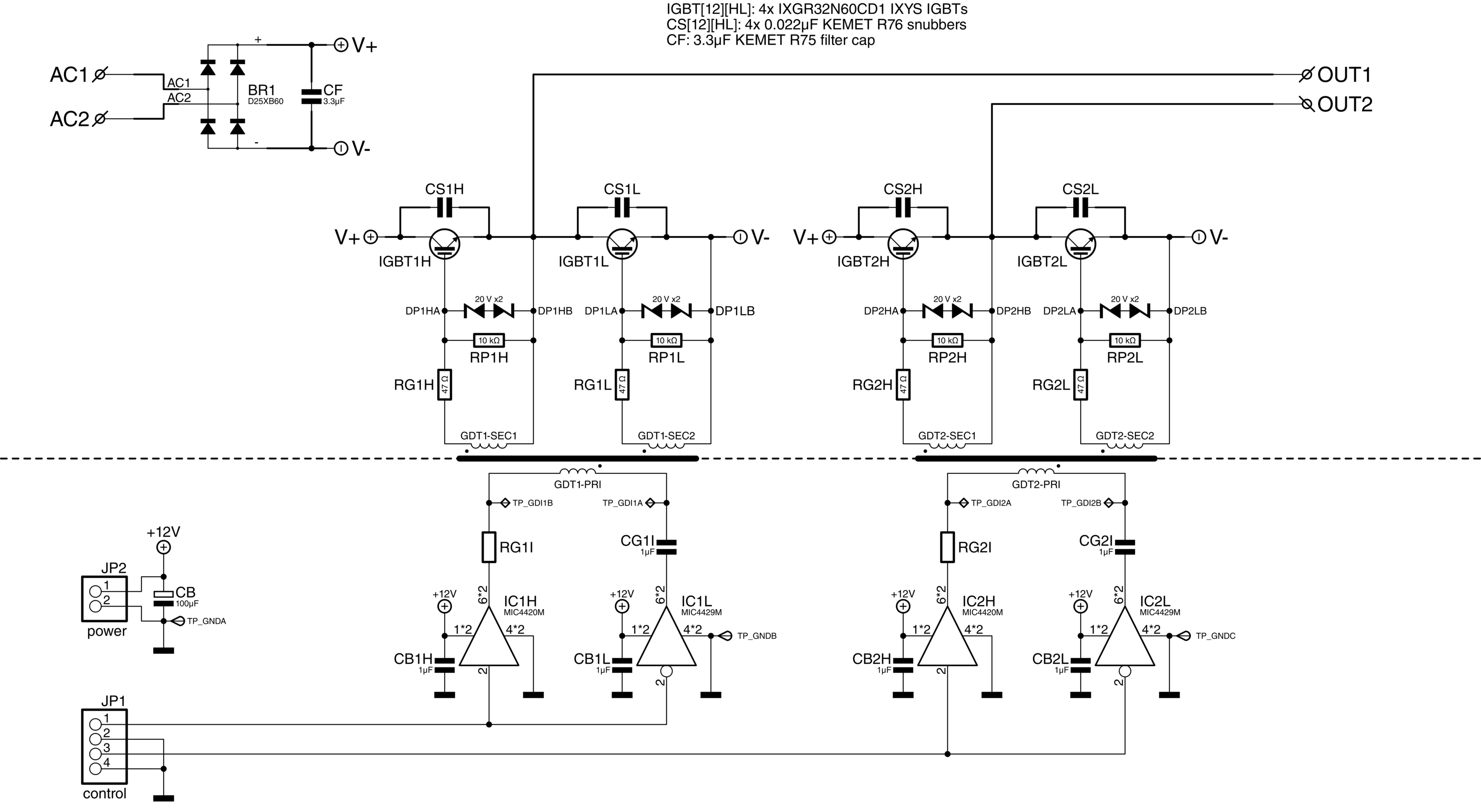
[[File:Induction_heater_power_stage_schematic.png]] | |||
Shown above is the schematic for the power stage. Mains voltage enters on the top left, where it is rectified and filtered to get approximately 325 V DC. Then, four IGBTs (IGBT1H, -1L, -2H, and -2L) form an H-bridge that generates the 10-100 kHz 'modified square wave' for the transformer. | |||
The | The IGBTs are driven via gate-drive transformers (GDT1 and GDT2) so that the control circuitry can be isolated from the high-voltage side. These transformers in turn are driven by high-current MOSFET drivers (IC1H, -1L, -2H, and -2L), which receive their signals from the controller. | ||
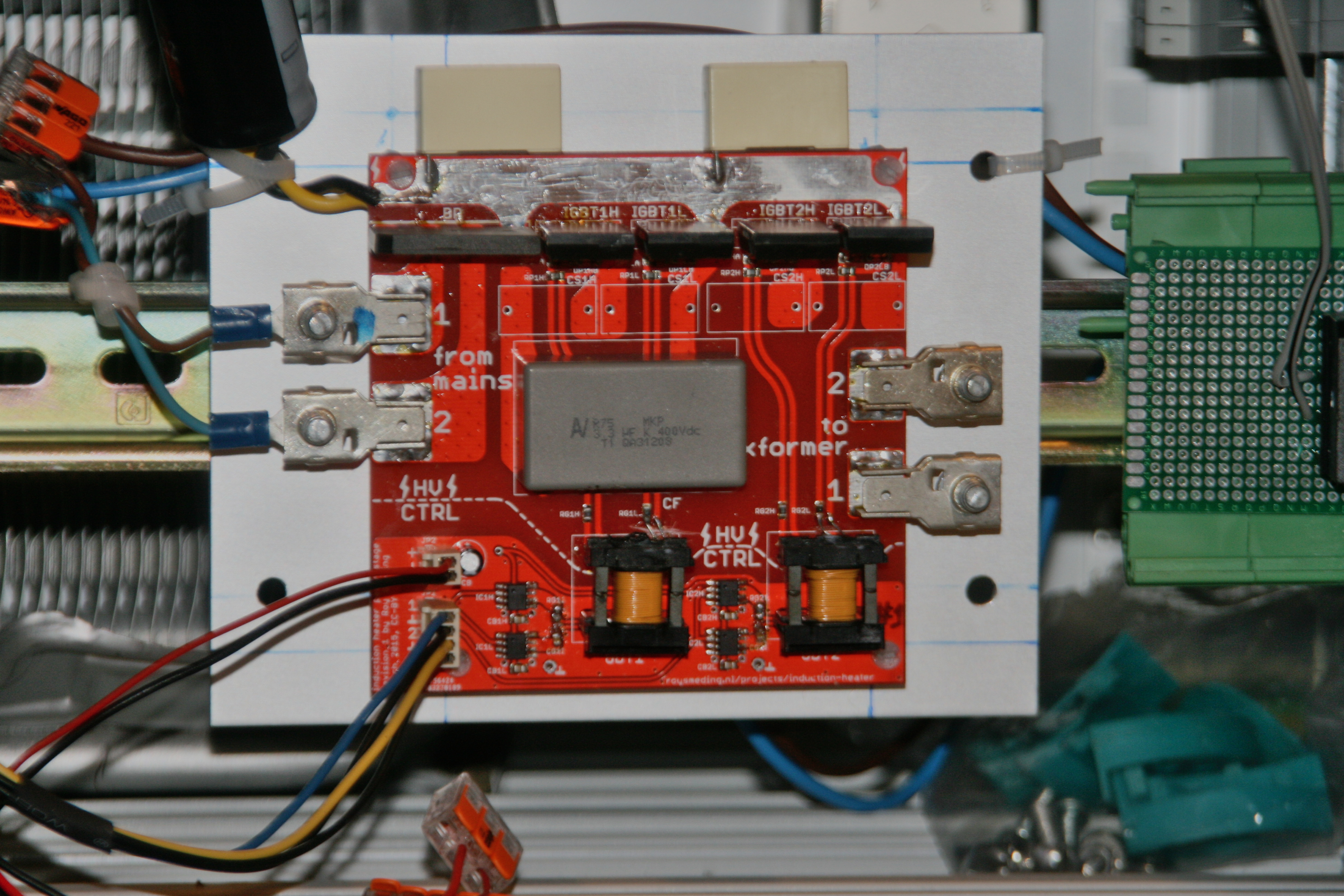
[[File:Induction_heater_power_stage_board_assembled.jpg]] | |||
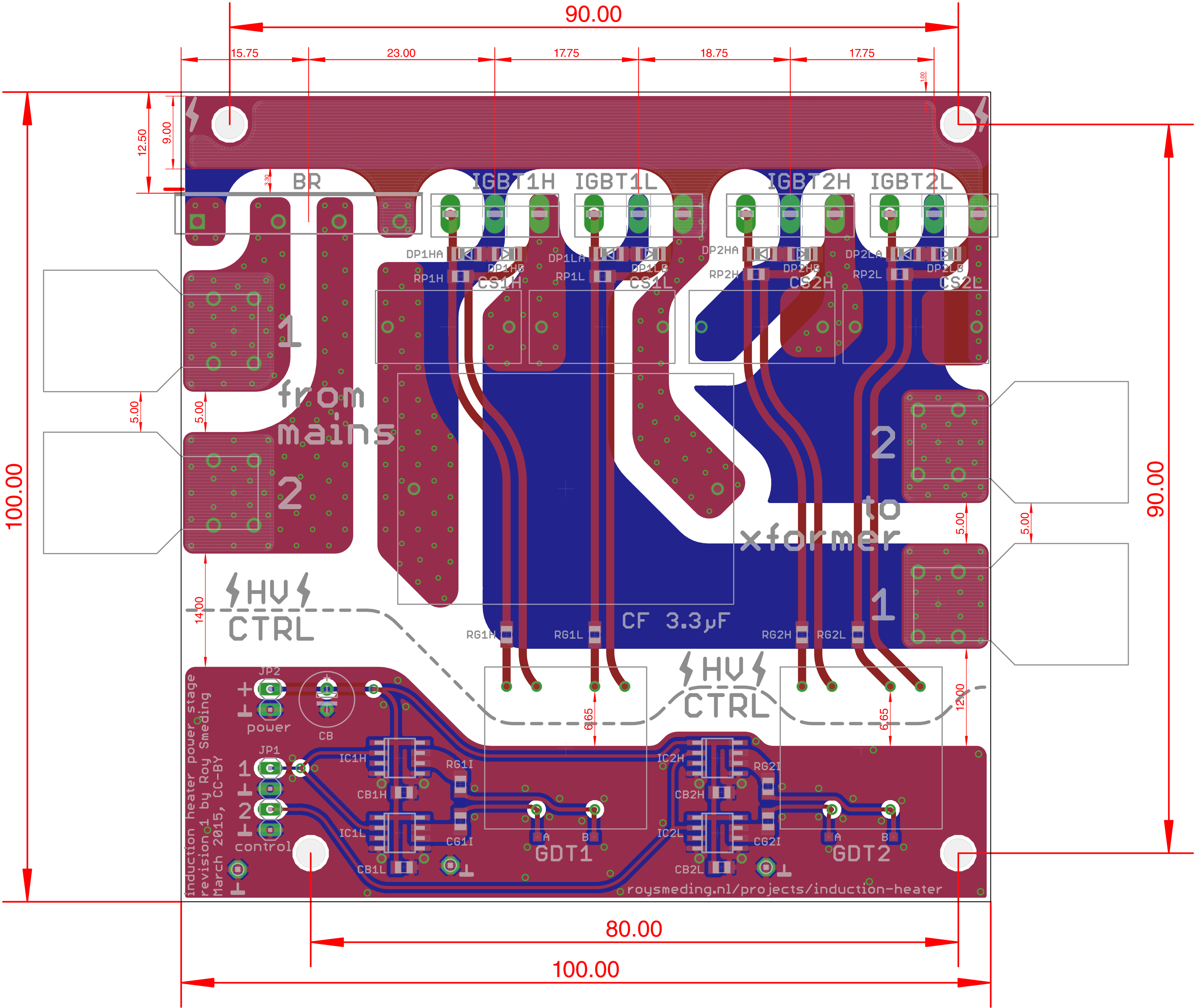
[[File:Induction_heater_power_stage_board_layout.png]] | |||
== Pledges == | == Pledges == | ||
Revision as of 18:35, 30 September 2016
| Project InductionHeater | |
|---|---|
| Status | In progress |
| Contact | smeding |
| Last Update | 2016-09-30 |
We're working on an induction heater that can be used to heat anything conductive to high temperatures. The plan is to try to use it for forging steel and melting aluminum.
Here are some examples of what a device like this is capable of:
System design
Induction heating works by applying a high-frequency magnetic field to the (conductive) workpiece being heated. Because of the skin effect, conduction at these frequencies only occurs in a thin layer on the outside of the workpiece. This acts like the secondary winding of a transformer, allowing current to flow and heating the workpiece through resistive heating.
The design consists of the following parts:
- The power stage rectifies mains voltage, which is then chopped into a high-frequency 'modified square wave' with variable duty cycle and frequency.
- The coupling transformer transforms the relatively high-voltage, low-current square wave into a lower-voltage, high-current one, to ease the requirements on the work coil.
- The work coil is where the workpiece is placed to be heated.
- The controller monitors relevant currents and voltages, and generates the waveforms that drive the power stage transistors.
Specs
- Input power: Standard single-phase mains: 230V RMS, 16A max ⇒ 3.5kVA
- Frequency: 10 kHz - 100 kHz
- 500A absolute maximum current in work coil
- 'Modified square wave' control: variable frequency and duty cycle
Power stage
Shown above is the schematic for the power stage. Mains voltage enters on the top left, where it is rectified and filtered to get approximately 325 V DC. Then, four IGBTs (IGBT1H, -1L, -2H, and -2L) form an H-bridge that generates the 10-100 kHz 'modified square wave' for the transformer.
The IGBTs are driven via gate-drive transformers (GDT1 and GDT2) so that the control circuitry can be isolated from the high-voltage side. These transformers in turn are driven by high-current MOSFET drivers (IC1H, -1L, -2H, and -2L), which receive their signals from the controller.
Pledges
So far, the following has been pledged:
- Gori: 50 euro
- Flok: 10 euro
- Walter: 50 евра
- FooBar: €20 cash betaald
- bertrik: €10
- Semafoor: €20
- Morphje: EUR 10 (and driving to the hardware store once)
Total pledges: €170


