STM32: Difference between revisions
| (22 intermediate revisions by the same user not shown) | |||
| Line 3: | Line 3: | ||
|Picture=HTB1PemDJpXXXXXHXpXXq6xXFXXXM.jpg | |Picture=HTB1PemDJpXXXXXHXpXXq6xXFXXXM.jpg | ||
|Omschrijving=STM32 setup guide | |Omschrijving=STM32 setup guide | ||
|Status= | |Status=Completed | ||
|Contact=bertrik | |Contact=bertrik | ||
}} | }} | ||
| Line 28: | Line 28: | ||
[http://www.oddwires.com/blog/using-a-generic-stm32-board-with-arduino Another, very similar, guide to getting started with STM32 and Arduino]. | [http://www.oddwires.com/blog/using-a-generic-stm32-board-with-arduino Another, very similar, guide to getting started with STM32 and Arduino]. | ||
There are several ways to program an STM32: | |||
* serial: using a built-in serial port bootloader, you need a USB-serial converter for this and you need to move some jumpers each time | |||
* stlink: using an ST-LINK programmer and 4 wires, clones can be found very cheaply on AliExpress (about E2,-) | |||
* stm32duino USB bootloader: after installing the bootloader once (using the serial method), you can rewrite a new program over USB, you just need a USB micro cable | |||
I like the STM32duino bootloader method. | |||
This way, you need to wire up a USB/serial conversion board and set/reset jumpers only once for bootloader installation and from that point on you can program the board over USB. | |||
== Setting up the tool chain == | == Setting up the tool chain == | ||
| Line 33: | Line 41: | ||
=== Linux specific === | === Linux specific === | ||
Some things | Some things you need to do on a system level: | ||
* uninstall the 'modemmanager' package, | * the usual stuff to add your user to the 'dialout' group so you have permission to access the serial port (log out and log in after this) | ||
sudo apt | sudo adduser <username> dialout | ||
* uninstall the 'modemmanager' package, it interferes with the serial port device created by the STM32duino bootloader | |||
sudo apt autoremove modemmanager | |||
* install the 32-bit libraries if you're on a 64-bit OS but using the 32-bit binaries (stmflash etc.) | |||
sudo apt install libc6-i386 | |||
=== Arduino IDE === | === Arduino IDE === | ||
| Line 56: | Line 68: | ||
=== Platform IO === | === Platform IO === | ||
Platformio allows you to build/upload/monitor Arduino programs without using the Arduino IDE (and more). | |||
All settings (which target, which libraries, etc) are stored in a platformio.ini file (instead of existing only as selections in the Arduino IDE). | |||
Below is an example platformio configuration for a blue pill with the USB bootloader. | Below is an example platformio configuration for a blue pill with the USB bootloader. | ||
Save this to a file named platformio.ini in the directory where the .ino file is, | Save this to a file named platformio.ini in the directory where the .ino file is. | ||
You can build the binary with 'pio run', upload it with 'pio run -t upload' and interact with your sketch over the serial port with 'pio device monitor'. | |||
<pre> | <pre> | ||
| Line 63: | Line 79: | ||
src_dir = . | src_dir = . | ||
[env: | [env:default] | ||
platform = ststm32 | platform = ststm32 | ||
board = | board = genericSTM32F103C8 | ||
framework = arduino | framework = arduino | ||
upload_protocol = dfu | upload_protocol = dfu | ||
</pre> | </pre> | ||
Note: don't use 'bluepill_f103c8' as board, it is not compatible with the stm32duino bootloader! | |||
== Hardware == | == Hardware == | ||
[[File:bluepill_pinout.png|right| | [[File:bluepill_pinout.png|right|thumb]] | ||
The hardware I'm using, is the [http://wiki.stm32duino.com/index.php?title=Blue_Pill blue pill], I soldered on the headers for easy plugging with dupont-wire. | The hardware I'm using, is the [http://wiki.stm32duino.com/index.php?title=Blue_Pill blue pill], I soldered on the headers for easy plugging with dupont-wire. | ||
I | === Pinout LQFP48 === | ||
[[File:stm32_lqfp48_pinout.png|right|thumb]] | |||
[http://www.olliw.eu/ OlliW] made a nice pinout diagram of the STM32 in the LQFP48 package, which I'm reproducing here (converted from JPG to PNG). | |||
=== Flashing the USB bootloader === | |||
The USB bootloader makes it easy/fast to upload new software into the board over USB. | |||
You need a USB-serial converter for this. | |||
Wire it up as follows: | |||
* converter 5V -> board 5V | * converter 5V -> board 5V | ||
* converter GND -> board GND | * converter GND -> board GND | ||
| Line 90: | Line 108: | ||
* converter TXD -> board A10 | * converter TXD -> board A10 | ||
For the blue pill the steps to install the bootloader are as follows: | |||
* clone the git archive containing the STM32 bootloaders: | |||
git clone https://github.com/rogerclarkmelbourne/STM32duino-bootloader | |||
* cd into the directory Arduino_STM32/tools/linux/stm32flash | |||
* set the BOOT0 jumper to the "1" position and the BOOT1 jumper to the "0" position, then push the reset button. | |||
* disable the flash-read protection: | |||
./stm32flash /dev/ttyUSB0 -k | |||
* flash the bootloader: | |||
./stm32flash -w ~/code/stm32/STM32duino-bootloader/binaries/generic_boot20_pc13.bin -v -g 0x0 /dev/ttyUSB0 | |||
* return both BOOT jumpers to the "0" position. | |||
== Software == | == Software == | ||
To load your application using the Arduino IDE: | To load your application using the Arduino IDE: | ||
* in the Arduino IDE, under menu Tools / Board, select "Generic STM32F103C Series" | * in the Arduino IDE, under menu Tools / Board, select "Generic STM32F103C Series" | ||
* in the Arduino IDE, under menu Tools / Upload Method, select " | * in the Arduino IDE, under menu Tools / Upload Method, select "STM32duino bootloader" | ||
* use the following program to blink the on-board LED: | * use the following program to blink the on-board LED: | ||
<pre> | <pre> | ||
| Line 113: | Line 139: | ||
} | } | ||
</pre> | </pre> | ||
* ctrl-U to upload it to the board, the program will start automatically | * ctrl-U to upload it to the board, the program will start automatically | ||
=== A/D converter === | |||
STM32 has built-in A/D converters, but how can you effectively use them? | |||
=== | |||
Useful references: | |||
* | * ~/.platformio/packages/framework-arduinoststm32-maple/STM32F1/libraries/STM32ADC/src is a kind of wrapper around utility/util_adc.h | ||
* https://deepbluembedded.com/stm32-adc-tutorial-complete-guide-with-examples/ | |||
= Future work = | = Future work = | ||
Latest revision as of 12:01, 18 December 2022
| Project STM32 | |
|---|---|

| |
| STM32 setup guide | |
| Status | Completed |
| Contact | bertrik |
| Last Update | 2022-12-18 |
Introduction

This page is about inexpensive microcontroller boards containing an STM32 processor and how to get them to work.
You can find these boards on AliExpress for less than €2,- if you search for "stm32f103c8t6". Yet they have nice specifications, see also http://www.st.com/en/microcontrollers/stm32f103c8.html
To name a few:
- 32-bit ARM Cortex-M3 processor running at up to 72 MHz
- 128 kB flash memory, 20 kB SRAM
- USB and CAN controllers
- 32 kHz crystal for RTC
- dual 1 us A/D converter, DMA controller
- the usual stuff like SPI, UART, I2C
They are even Arduino compatible, see:
- Arduino for STM32
- Arduino goes STM32, a quick tutorial
- Arduino STM32 page of Roger Clark
Another, very similar, guide to getting started with STM32 and Arduino.
There are several ways to program an STM32:
- serial: using a built-in serial port bootloader, you need a USB-serial converter for this and you need to move some jumpers each time
- stlink: using an ST-LINK programmer and 4 wires, clones can be found very cheaply on AliExpress (about E2,-)
- stm32duino USB bootloader: after installing the bootloader once (using the serial method), you can rewrite a new program over USB, you just need a USB micro cable
I like the STM32duino bootloader method. This way, you need to wire up a USB/serial conversion board and set/reset jumpers only once for bootloader installation and from that point on you can program the board over USB.
Setting up the tool chain
This describes the steps I did to get a "blue pill" board to work on Debian Jessie.
Linux specific
Some things you need to do on a system level:
- the usual stuff to add your user to the 'dialout' group so you have permission to access the serial port (log out and log in after this)
sudo adduser <username> dialout
- uninstall the 'modemmanager' package, it interferes with the serial port device created by the STM32duino bootloader
sudo apt autoremove modemmanager
- install the 32-bit libraries if you're on a 64-bit OS but using the 32-bit binaries (stmflash etc.)
sudo apt install libc6-i386
Arduino IDE
Steps to set up the IDE:
- get and install the latest Arduino IDE from here.
- under menu Tools / Board / Board Manager, search for "zero" and install the Arduino Zero toolchain
- get the Arduino_STM32 source code, for example, run in the console:
cd ~/code
mkdir stm32
cd stm32
git clone https://github.com/rogerclarkmelbourne/Arduino_STM32
- create a symlink to the Arduino_STM32 source tree in your ~/Arduino/hardware directory, for example:
cd ~/Arduino/hardware
ln -s ~/code/stm32/Arduino_STM32 .
- restart the Arduino IDE.
Platform IO
Platformio allows you to build/upload/monitor Arduino programs without using the Arduino IDE (and more). All settings (which target, which libraries, etc) are stored in a platformio.ini file (instead of existing only as selections in the Arduino IDE).
Below is an example platformio configuration for a blue pill with the USB bootloader. Save this to a file named platformio.ini in the directory where the .ino file is. You can build the binary with 'pio run', upload it with 'pio run -t upload' and interact with your sketch over the serial port with 'pio device monitor'.
[platformio]
src_dir = .

[env:default]
platform = ststm32
board = genericSTM32F103C8
framework = arduino
upload_protocol = dfu
Note: don't use 'bluepill_f103c8' as board, it is not compatible with the stm32duino bootloader!
Hardware

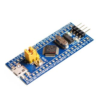
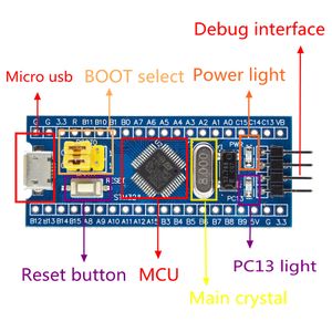
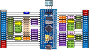
The hardware I'm using, is the blue pill, I soldered on the headers for easy plugging with dupont-wire.
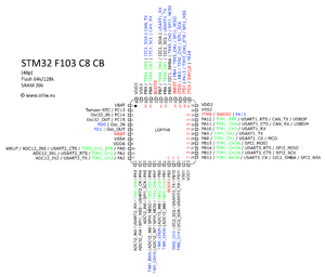
Pinout LQFP48

OlliW made a nice pinout diagram of the STM32 in the LQFP48 package, which I'm reproducing here (converted from JPG to PNG).
Flashing the USB bootloader
The USB bootloader makes it easy/fast to upload new software into the board over USB.
You need a USB-serial converter for this.
Wire it up as follows:
- converter 5V -> board 5V
- converter GND -> board GND
- converter RXD -> board A9
- converter TXD -> board A10
For the blue pill the steps to install the bootloader are as follows:
- clone the git archive containing the STM32 bootloaders:
git clone https://github.com/rogerclarkmelbourne/STM32duino-bootloader
- cd into the directory Arduino_STM32/tools/linux/stm32flash
- set the BOOT0 jumper to the "1" position and the BOOT1 jumper to the "0" position, then push the reset button.
- disable the flash-read protection:
./stm32flash /dev/ttyUSB0 -k
- flash the bootloader:
./stm32flash -w ~/code/stm32/STM32duino-bootloader/binaries/generic_boot20_pc13.bin -v -g 0x0 /dev/ttyUSB0
- return both BOOT jumpers to the "0" position.
Software
To load your application using the Arduino IDE:
- in the Arduino IDE, under menu Tools / Board, select "Generic STM32F103C Series"
- in the Arduino IDE, under menu Tools / Upload Method, select "STM32duino bootloader"
- use the following program to blink the on-board LED:
#define pinLED PC13

void setup() {
  pinMode(pinLED, OUTPUT);
}

void loop() {
  digitalWrite(pinLED, HIGH);
  delay(200);
  digitalWrite(pinLED, LOW);
  delay(100);
}
- ctrl-U to upload it to the board, the program will start automatically
A/D converter
STM32 has built-in A/D converters, but how can you effectively use them?
Useful references:
- ~/.platformio/packages/framework-arduinoststm32-maple/STM32F1/libraries/STM32ADC/src is a kind of wrapper around utility/util_adc.h
- https://deepbluembedded.com/stm32-adc-tutorial-complete-guide-with-examples/
Future work
Actually build something with an STM32!
Ideas:
- a LoRaWAN node for The-Things-Network
- a bat call recorder, this thing is faster and has more memory than the LPC2148 in my previous bat call recorder prototype
Investigate the Blackmagic debugging firmware. This should allow you to debug your applications (e.g. step through code in an IDE such as eclipse). See also: