Doorduino1: Difference between revisions
Some notes |
No edit summary |
||
| (4 intermediate revisions by 3 users not shown) | |||
| Line 1: | Line 1: | ||
'''This page describes Doorduino 1, that was used at our old location, Binckhorstlaan 172. Please refer to [[Doorduino2]] for more up-to-date information.''' | |||
{{Project | {{Project | ||
|Name= | |Name=Doorduino1 | ||
|Status=Completed | |Status=Completed | ||
|Contact=gmc | |Contact=gmc | ||
| Line 160: | Line 163: | ||
Some notes on which the new design is based: | Some notes on which the new design is based: | ||
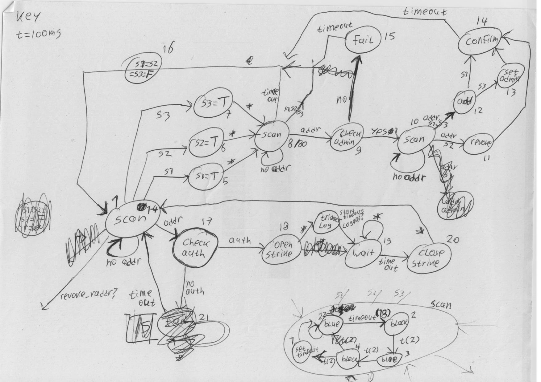
* [[File: | * [[File:revdoor1.png]] | ||
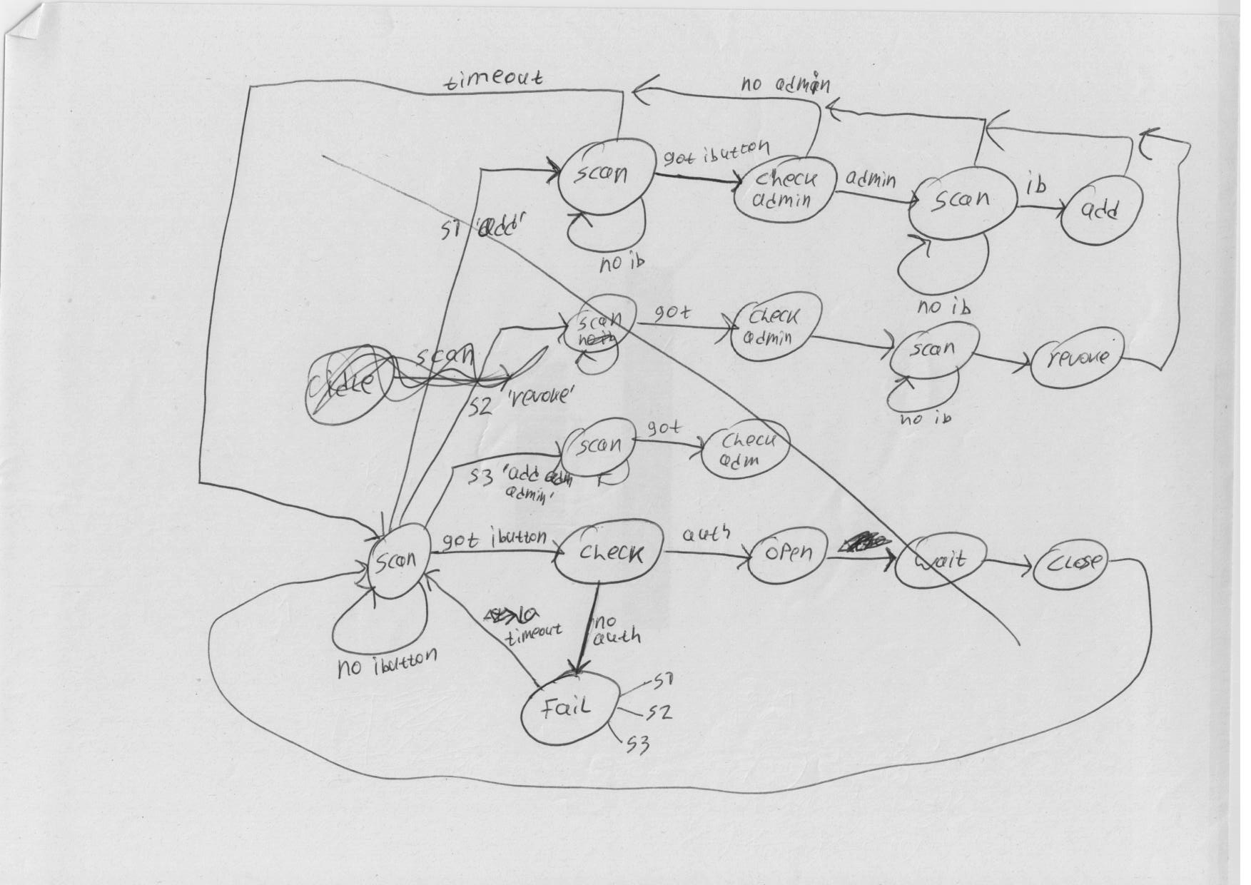
* [[File: | * [[File:revdoor2.png]] | ||
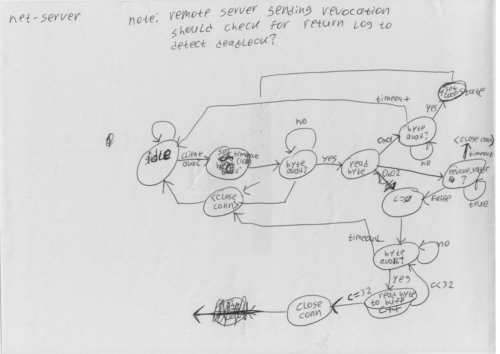
* [[File: | * [[File:revdoor4.png]] | ||
* [[File: | * [[File:revdoor5.png]] | ||
* [[File: | * [[File:revdoor6.png]] | ||
Latest revision as of 22:53, 13 January 2013
This page describes Doorduino 1, that was used at our old location, Binckhorstlaan 172. Please refer to Doorduino2 for more up-to-date information.
| Project Doorduino1 | |
|---|---|
| Status | Completed |
| Contact | gmc |
| Last Update | 2013-01-13 |
Old, metal keys have certain disadvantages, one being that they are not easy to revoke when compromised (unless you invest in really expensive lock systems). So the create a good SpaceAccess system, we will be using the following:
Several ideas have been passed around on IRC: SMS-based challenge/response, wifi with ssh logon to unlock the door, something USB based (yubikey's) and finally iButton one-wire devices.
After a short trial with the yubikeys we settled on one-wire devices.
The resulting system is also mentioned on hackcess.org.
One-Wire iButton
iButton's are small metal can's (about the size of a 10 ct coin, 5mm deep) that house a small chip inside. The chip has a unique identifier and optionally some memory, sensors and processing capability. The chip communicates using 1 signal and 1 ground wire, connected to the top and sides of the can. By pressing the can onto a reader/holder it can communicate to other devices on the one-wire bus.
There are many ways to interface with a one-wire bus, using either serial, usb, i2c, parallel or custom interfaces. Our initial tests were done using some id-only iButtons and a iButton socket connected to an arduino. This worked quite well, and we managed to get the basics working in a matter of minutes (wonderful since we had neither experience with one-wire devices or with programming the arduino). For a more permanent solution we wanted to interface directly to a pc's serial port. We settled on a one-wire to serial interface chip, the DS2480B+ (http://www.maxim-ic.com/quick_view2.cfm/qv_pk/2923).
However, the solution with the serial port and pc appeared finicky, partly because we did not create an SMD board but soldered wires to the tiny chips. Also, the pc solution is somewhat more involved to set up in such a way that the electronic lock still works when the power is down. Therefore, we went back to arduino, and implemented the whole thing as an autonomous system based on an arduino, some code and a handful of hardware.
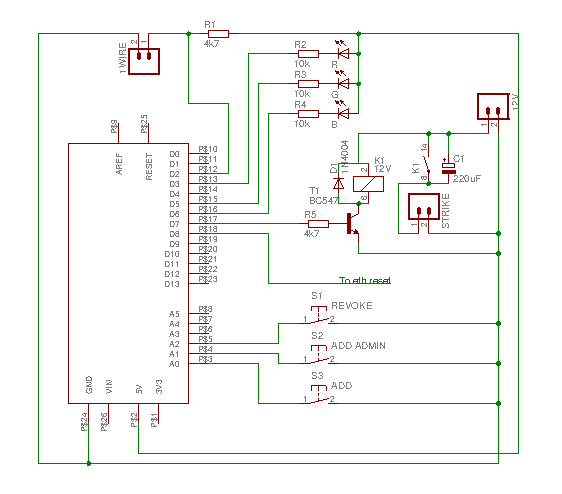
Wiring diagram
Arduino shield
Update: pin A4 is connected to a relay on the legacy remote door opening system, and is pulled to ground to trigger opening of the door.
Pin D8 is connected to the reset pin of the ethernet shield. I had to bend the reset pin of the ethernet shield so that it does not connect to the arduino itself. This is necessary for the old-design ethernet shield, which does not have a reset circuit on-board and will not initialize properly on power-up. There is code in the arduino sketch to manually reset the ethernet shield from within the program.
What this is still missing is a zener to protect against power surges on the one-wire bus, and perhaps some protection against 12v going back into the arduino if T1 shorts. Of course, you could use a CC instead of a CA RGB led.
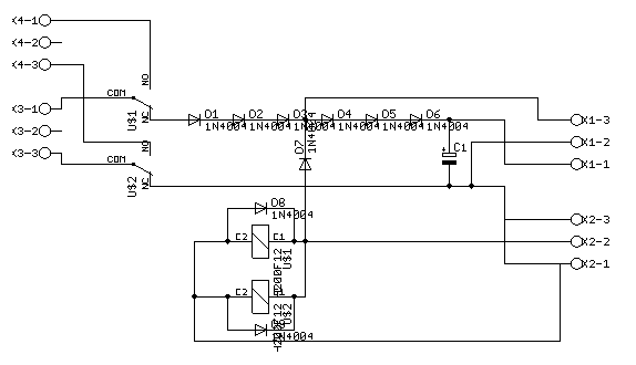
Battery backup unit
Connections:
- K4-1: charger +
- K4-3: charger -
- K3-1: battery +
- K3-3: battery -
- K1-3: ~12V to arduino shield
- K1-2: GND
- K1-1: ~9V to arduino VIN
- K2-3: GND
- K2-2: +12V from mains power
- K2-1: GND
We're using a 12V 7.2Ah lead-battery, with intelligent charger to keep the battery charged without overcharging.
PCB film (postscript, A4): [1]
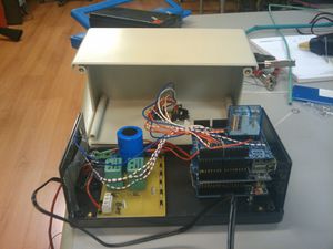
Top view of the bbu with parts: 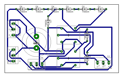
oneWire use-case descriptions
OPT denotes steps that are optional when we add an ethernet shield
- Initialisation:
- arduino board is loaded with software to zero the EEPROM
- arduino board is loaded with the space access control software
- led blinks blue
- first key is scanned, and will be stored in EEPROM as an admin key
- OPT: server is contacted to register admin key
- led blinks green twice
- system is now ready for use
- Adding new keys:
- the 'add normal' (button '1') or 'add admin' (button '2') button is pressed
- led will blink blue
- an admin key is scanned (if not within 10 seconds, abort)
- led will blink yellow
- the key to be added is scanned
- the key will be added, or if already in the db it's access rights (admin or not) will be set
- OPT: server is contacted to register new key or change key details
- led will blink green
- after 10 seconds, back to normal operation
- Revoking keys:
- the 'revoke' (button '3') button is pressed
- led will blink blue
- an admin key is scanned (if not within 10 seconds, abort)
- led will blink yellow
- the key to be revoked is scanned
- if existing key:
- key is removed from EEPROM
- OPT: server is contacted to revoke key
- led blinks green for 10 seconds
- if non-existing key:
- led blinks red for 10 seconds
- Normal operation:
- led will be on constantly, blue
- OPT: server is contacted every 60 seconds, asking for revocations, revoked keys are removed from EEPROM
- key is scanned
- when good key
- led will turn green
- door opens
- OPT: server is contacted, logging key
- after 10 sec back to normal operation
- when bad key
- led will turn red
- after 10 sec back to normal operation
Arduino code
This code on github implements the above more-or-less.
Server
The server keeps a shadow db of the programmed keys. This will probably be in the LDAP database, and the revocation list is sent to the arduino when the arduino asks for this, one key at a time. The server can keep additional information about the key, eg it's owner.
When access is granted, the sha256 hash of the key's address is sent to the server over http.
When a key is to be revoked, the server responds with a sha256 hash of secret1 (an arbitrary string, shared between server and arduino) and the key address. Before deleting the key from the EEPROM, the arduino will send a sha256 hash of secret2 and the key address to the server to confirm it has received the revocation request.
Status led feedback
The system has an RGB led for visual feedback, this table will allow you to understand what different color/state combinations mean and what it is doing.
| Color | State: Steady | State: Blinking |
|---|---|---|
| Blue | Idle | Waiting for admin key |
| Yellow | - | Waiting for parameter/secondary key |
| Green | Access granted | Command confirmed |
| Red | Access denied | Command failed |
| Purple | Checking & processing remote revocation list | - |
Remaining issues
- Need a lock-motor instead of an electronic strike, for extra security
- Metal profile to prevent carding
Site Info
- The doorduino communicates with the webserver on 'lcd'.
- Webserver files are on fuse:/var/spool/jails/lcd/fsroot/usr/local/www/sites/lcd or lcd:/usr/local/www/sites/lcd
Refactoring
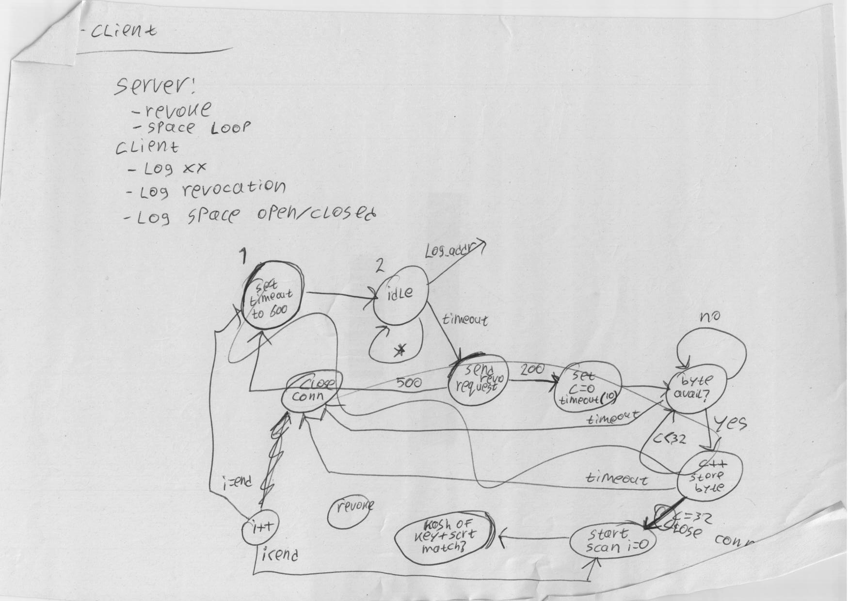
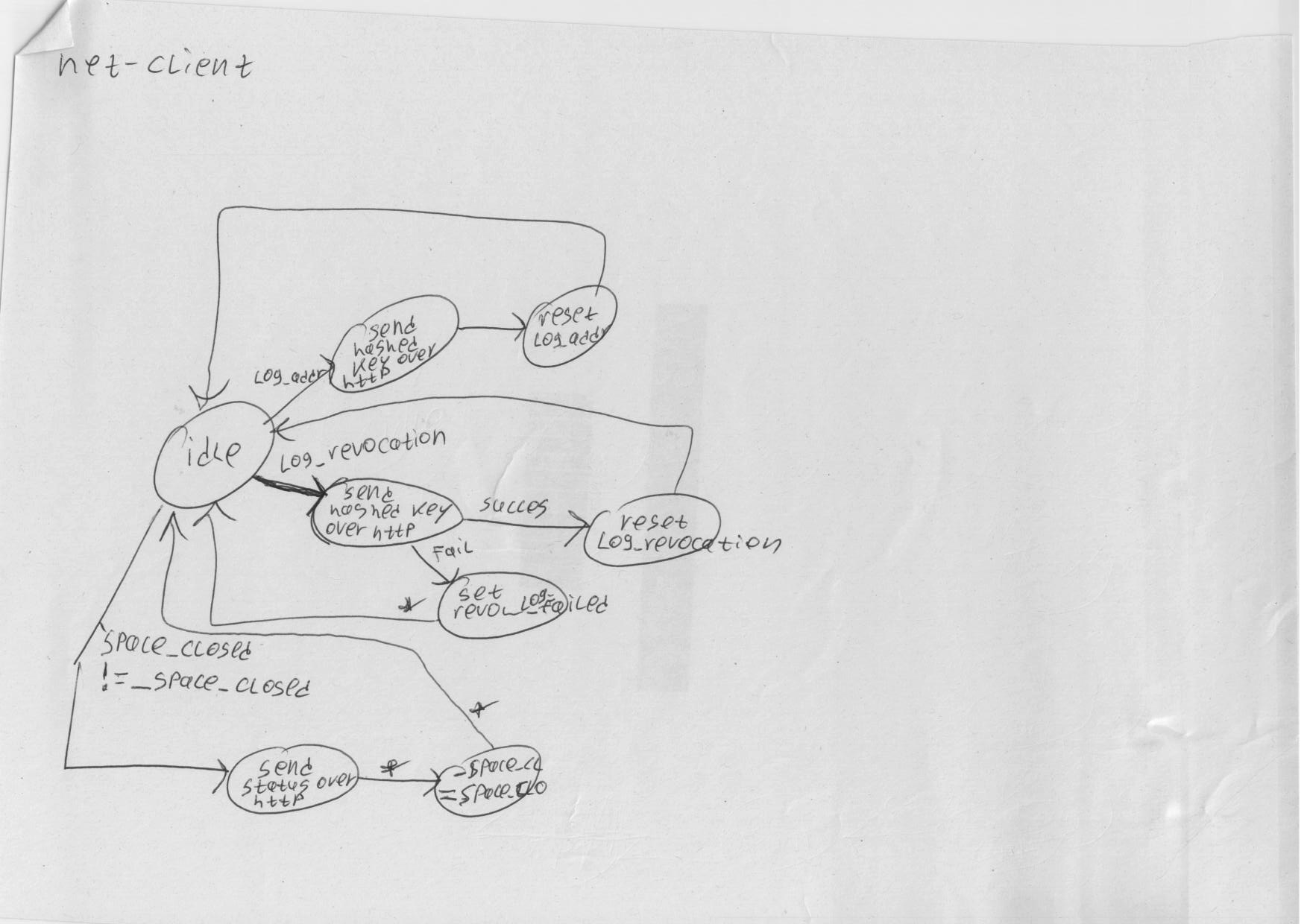
Some notes on which the new design is based:
