LichtKrant: Difference between revisions
| Line 254: | Line 254: | ||
This display could be used as a kind of mirror of the main LED banner, except with no blue color component and 80x7 LEDs instead of 80x8. | This display could be used as a kind of mirror of the main LED banner, except with no blue color component and 80x7 LEDs instead of 80x8. | ||
For example, we could put it up at the kitchen and get notified of people opening doors, doorbell, etc. | For example, we could put it up at the kitchen and get notified of people opening doors, doorbell, etc. | ||
Requirements: | |||
* Make it electrically safe: a "cage" style power supply should be contained | |||
* Don't put it in the lounge, we'd like to keep the lounge clear of attention-grabbing / flashing stuff. The kitchen would be fine. | |||
Problems: | Problems: | ||
Revision as of 10:00, 14 January 2020
| Project LichtKrant | |
|---|---|

| |
| Controller for 3-colour 80x7 pixel moving LED sign | |
| Status | Completed |
| Contact | bertrik |
| Last Update | 2020-01-14 |
Status
Status as of 2020/1/13:
- Reverse engineered it, I know how it works and documented it
- Software works, allowing arbitrary bitmap graphics to be sent over WiFi. The sign can show 4-bit gradients in both red and green, essentially it now has 8-bit colors instead of 2-bit.
- The power supply that came with it (5V, 4A) broke down. At full brightness, the display actually uses about 6A, so it seems to be under-dimensioned anyway. A new one costs E20,- (ex shipping)
- Integration into revspace infrastructure requires more work:
- write a frame buffer forwarder and fix the linux package manager on the raspberry pi of the 'ledbanner'
- make it completely "space-approved"
- I don't feel like doing the above
In other words, learned a lot, but I'm done with it.
Movie: https://www.youtube.com/watch?v=P8D3vtvg2U4
Introduction
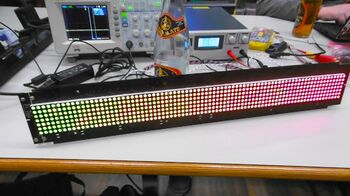
Found a moving LED sign on the revspace free stuff table.
It is 80 pixels wide, 7 pixels high. Each pixel has two sub-pixels (red and green) that can be turned on or off, so it can display 3 colours (off, red, orange, green)
Hacked it, so now we have the following:
- reverse engineered the electronics and documented how it works
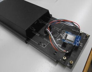
- replaced the controller board with an ESP8266, so we can receive image/text updates over the network
- implemented more colour depth, so we can display gradient bitmaps (not just red/green/orange but any color in between)
- wrote software for this and published it
Reverse engineering
It consists of a processor board and a LED board.
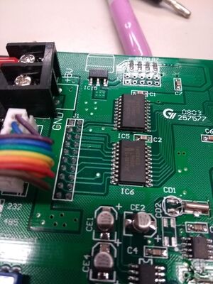
Processor board
The processor board has a 8052, a flash chip, battery, 32768 Hz crystal, 40 MHz crystal, Altera Max chip. It appears the Altera chip drives two 245 chips which in turn drive the signal to the connector J1 to the LED board.
It takes 5V as input.
The PCB has a text on it: HXITC017_2.PCB
LED board
The LED board contains the actual pixels, organized in 16 modules of 5x7 LEDs. Each LED has a red sub-pixel and a green sub-pixel, so it can do colors: red, green, orange. The LED modules have the text GYXM-G2357ASRG on them.
The PCB has a text on it: HXBI80070509.PCN, date 2007-12-28
The are already electronics on it, consisting mostly of 595 chips (serial shift registers). The are two chains of 10 pieces of 74hc595 chips each, controlling the columns. There is an '138 chip (3-to-8 decoder) that drives a set of MOSFETS, 7 in total, controlling the rows. The MOSFETs are SDM4953, dual P-channel MOSFETs.
How does it work
Finding out how it works is done by tracing out the connections from connector J1, which connects the processor board to the LED board.
*  J1.1: IC2.A1 -> IC2.B1 -> via ... -> shift clock
                -> IC1.B1 -> IC1.A1 -> U11.SRCLK
                -> IC1.B6 -> IC1.A6 -> U1.SRCLK
*  J1.2: GND
*  J1.3: IC2.A2 -> IC2.B2 -> via ... -> latch clock
*                      IC1.B2 -> IC1.A2 -> U11.RCLK
*                      IC1.B5 -> IC1.A5 -> U1.RCLK
*  J1.4: GND
*  J1.5: IC1.B3 -> IC1.A3 -> U11.SER -> data pin for upper shift register (green)
*  J1.6: GND
*  J1.7: IC1.B4 -> IC1.A4 -> U1.SER -> data pin for lower shift register (red)
*  J1.8: GND
*  J1.9: IC2.A7 -> IC2.B7 -> via ... -> row enable
         IC4.1A -> IC4.1Y -> IC3.G2B
* J1.10: VCC
* J1.11: IC2.A3 (row) -> IC3.A -> row select
* J1.12: VCC
* J1.13: IC2.A4 (row) -> IC3.B -> row select
* J1.14: VCC
* J1.15: IC2.A5 (row) -> IC3.C -> row select
* J1.16: J4 (IR receiver)
* J1.17: IC2.A6 -> IC2.B6 -> IC3.G2A -> frame enable, appears to have a pull-up already, so can be left unconnected
* J1.18: ???
* J1.19: ???
* J1.20: connected to the "ethernet" dipswitch
- IC1 = 74HC245 (octal buffer) on LED board
- IC2 = 74HC245 (octal buffer) on LED board
- IC3 = 74HC138 (3-8 mux) on LED board
- IC4 = 74HC04 (hex inverter) on LED board
- U1-U10 = lower chain of 74HC595 (8-bit shift register)
- U11-U20 = upper chain of 74HC595 (8-bit shift register)
The 74HC138 has an enable consisting of three signals G1, G2A, G2B. Signal G1 is connected to Vcc. Signal G2A is connected to B6 Signal G2B is connected through a hex inverter (IC4.1Y) -> IC4.A -> IC2.A7 -> IC2.B7
There are 8 rows (3 bits) controlled by the 74HC138 and 8 MOSFETS and two chains of 10x 74HC595 (8-bit shift registers) for the columns.
In summary, connector J1 has the following signals:
- columns
- 1 bit shift clock shared for both shift registers (J1.1)
- 1 bit latch clock shared for both shift registers (J1.3)
- 1 data bit for 80-bit shift register 1 (J1.5)
- 1 data bit for 80-bit shift register 2 (J1.7)
- rows
- 2 bits row enable (J1.9 and J1.17)
- 3-bits row select (J1.11, J1.13, J1.15)
- other
- 5V signals
- GND signals
- some signal for the infared remote control
Levels on the bus are 5V.
Theory of operation:
- software writes two rows (red and green) of 80 bits into the shift register, using the shift clock lines and two SER lines
- software latches the data from the shift registers into the LED row output registers
- software selects a row using the three rows select lines and the row enable signals
- wait a few ms while the LED row it lit
- next row
Timing
Some measurements on the timing of the signal with the original control board connected.
- The bit shift clock is about 300 ns high, 300 ns low. Frequency about 1.67 MHz.
- Row bytes are sent with an 9.6 us interval.
- The column latch clock pulses with an interval of 384 us, it's a positive going pulse about 300 ns long. This means a line rate of about 2.6 kHz.
- Row enable on J1.9 has an interval of 384 us, with a low-time of about 80 us.
- Row enable on J1.17 has an interval of about 6.16 ms, with a low-time of about 3.08 ms. This is relatively slow. My guess is that this is a kind of global brightness control PWM signal.
Columns:
- J1.11 (row select): 0.37 ms high, 0.37 ms low
- J1.13 (row select): 0.76 ms high, 0.76 ms low
- J1.15 (row select): 1.5 ms high, 1.5 ms low
-> the rows cycle through 8 states (although there are only 7 rows) -> the entire cycle takes about 3 ms, so the frame rate is about 300 Hz -> each row is enabled for 0.37 ms, consistent with the row column latch interval
Power consumption
The duty cycle of the LEDs is strongly determined by the row enable pins. It appears that J1.17 is used by the original control board to set the global brightness.
- all LEDs off, about 20 mA
- all red LEDs on, about 4.0 A
- all green LEDs on, about 3.7 A
- all LEDs (red + green) on, about 6.4 A
Hardware modifications
So far I've made the following modifications:
- soldered a power connector on the center of the display PCB, on the footprint that was already present, 5V is supplied there (up to 6 Amps!)
- removed the controller board
- added a Wemos D1 mini board, pinout:
| J1 connector | Wemos D1 mini | Remark |
|---|---|---|
| J1.1 | D8 | Column data shift |
| J1.3 | D7 | Column data latch |
| J1.5 | D6 | Green data |
| J1.7 | D5 | Red data |
| J1.8 | G | Ground |
| J1.9 | D4 | Row enable |
| J1.10 | 5V | 5V from LED board to Wemos D1 mini |
| J1.11 | D3 | Row select bit 0 |
| J1.13 | D2 | Row select bit 1 |
| J1.15 | D1 | Row select bit 2 |
Software
The code can be found in the github lichtkrant repository.
To compile it, you can use platformio. Install it (on Debian Linux for example) using:
 sudo apt install python3-pip
 sudo pip3 install platformio
Then compile and upload the software to the ESP8266 using:
pio run -t upload
Driving the pixels
The pixels are drawn entirely in an interrupt handler connected to timer1. The interrupt handler draws exactly one row on the display, by writing the 74HC595 column registers and setting the 74HC138 row multiplexer.
The timer runs at a line frequency of 4 kHz, resulting of a frame rate of 1/8th of that, or 500 Hz.
By using the timer interrupt, we get steady timing for lighting each row/line for exactly the same duration. The main execution context is still free to do other stuff.
Variable pixel brightness
Variable pixel is implemented using a kind of duty-cycle/dithering modulation that flashes the pixels on/off:
- For each pixel we keep a running brightness count (e.g. 8-bit).
- At each frame start, for each pixel, we add the brightness value from the frame buffer to the brightness count (e.g. 0-255). If the addition results in an overflow, the pixel is lit on the display, otherwise it is dimmed. For example, adding a brightness value of 128 causes the addition to overflow every other time, causing a 50%/50% duty cycle at half the update frequency.
- The running brightness count is initialized with a random number, this avoids synchronized flashing of the pixels on the display. In other words, pixels with the same brightness have the same duty cycle, but have staggered turn-of/turn-off times with respect to each other.
- The above is implemented for the red and green pixels separately.
RAW RGB interface
RAW RGB frames (80x8x3 bytes) can be sent over TCP to port 1234. The blue (B) channel is ignored, as is the lowest line of the 80x8 raw RGB frame.
For example, to render a text using ImageMagick and display it:
convert -size 80x10 -crop 80x8+0+2 -font 8-BIT\ WONDER.TTF -pointsize 9 -fill red -background black caption:"AweSome" -depth 8 rgb:- |netcat esp-ledsign.local 1234
(The 8-bit wonder font can be found at https://www.dafont.com/8bit-wonder.font )
For example, to display an animated GIF:
convert metaballs.gif rgb:- |netcat -q0 esp-ledsign.local 1234
(metaballs.gif was generated using https://github.com/bertrik/nyancat )
The software contains an mDNS responder that allows the network interface to be addressed as esp-ledsign.local (instead of using the ipv4 address).
Command interpreter
There is a simple command interpreter running on the serial port at 115200 bps. Type 'help' to see a list of commands.
Integration into revspace infrastructure
This display could be used as a kind of mirror of the main LED banner, except with no blue color component and 80x7 LEDs instead of 80x8. For example, we could put it up at the kitchen and get notified of people opening doors, doorbell, etc.
Requirements:
- Make it electrically safe: a "cage" style power supply should be contained
- Don't put it in the lounge, we'd like to keep the lounge clear of attention-grabbing / flashing stuff. The kitchen would be fine.
Problems:
- the ledbanner needs a way to access the esp-ledsign by name, e.g. using esp-ledsign.local, this could be done using avahi -> the ledbanner repository setup is messed up (try 'dnf install avahi-deamon' for example, no longer works)
- a way needs to be written that taps the graphics from the ledbanner and forwards it to the esp-ledsign
One solution is to write a little program:
- takes one full frame from stdin
- outputs that same frame to stdout
- duplicates the frame to a TCP connection to esp-ledsign.local over port 1234
- put this into the chain of applications processing ledbanner data on the ledbanner pi.
- essential is that it forwards the full frame and does not block doing this when the led sign is non-responsive / has a connect error / etc.
Links
Possibly useful other info:
- https://medium.com/@tharindu_peiris/p10-led-display-panel-using-esp8266-wemos-d1-mini-nodemcu-1e463ad60722
- some fonts for rendering text on 7-pixel high https://damieng.com/blog/2011/02/20/typography-in-8-bits-system-fonts
- atari font, almost entirely 7-pixels high https://www.bigmessowires.com/atarifont.png

