Reflow Oven: Difference between revisions
No edit summary |
mNo edit summary |
||
| Line 18: | Line 18: | ||
Over time, these data are reported here. | Over time, these data are reported here. | ||
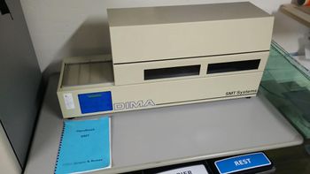
The particular model we have looks like a SMRO-0170 (to be confirmed). | The particular model we have looks like a DIMA SMT Systems SMRO-0170 (to be confirmed). | ||
In [http://www.neikorea.com/download/DIMA_catalog.pdf this document] is it referred to as the "Piccolo", with a maximum PCB size of 250x150mm. | In [http://www.neikorea.com/download/DIMA_catalog.pdf this document] is it referred to as the "Piccolo", with a maximum PCB size of 250x150mm. | ||
Revision as of 17:48, 26 March 2017
| Project Reflow Oven | |
|---|---|

| |
| Status | Completed |
| Contact | Crashjuh |
| Last Update | 2017-03-26 |
Because modern electronics components are tending more and more towards becoming SMD-only, and because the associated size reduction can also be very useful for space projects, we need a reflow oven.
Status
Oven has been acquired. It is a cheap 1kW Everglades toaster oven and has been able to do very crude reflow.
A prototype for the controller has been built and successfully measures temperature. I (smeding) am currently hammering out the PID loop to keep it at a fixed temperature. After that, all it needs is a little bit of UI and we should be good to go.
We now have a real reflow oven and currently we are testing what the best settings are. Over time, these data are reported here.
The particular model we have looks like a DIMA SMT Systems SMRO-0170 (to be confirmed). In this document is it referred to as the "Piccolo", with a maximum PCB size of 250x150mm.
Use by Revspace
The oven has 10 memory locations (Program number 01 till 10). At the moment we only have programmed program number 01. We program the programs for different PCB thicknesses.
| Program number | PCB Thickness | |
|---|---|---|
| 01 | 1.5 / 1.6 mm | |
| 02 | xx | |
| 03 | xx | |
| 04 | xx | |
| 05 | xx | |
| 06 | xx | |
| 07 | xx | |
| 08 | xx | |
| 09 | xx | |
| 10 | xx |
- Program number:
Enter : 01
- Preheat standby:
Enter : 080
- Preheat standby:
- Preheat airtemp:
Enter : 150
- Preheat airtemp:
- Preheat time:
Enter : 02:00
- Preheat time:
- Solder temp. :
Enter : 250
- Solder temp. :
- Solder time:
Enter : 01:30
- Solder time:
- Learn preheat:
Enter : 000
- Learn preheat:
- Learn solder:
Enter : 000
- Learn solder:
Gallery
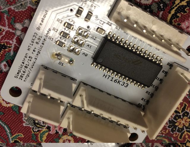
I2C Led driver breakout board, D1 was hand-soldered. Solder paste was applied using a Mylar stencil cut with the revspace lasercutter.
 (Image: robv)