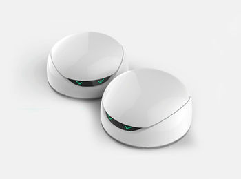
Luteijn/Vortex

From RevSpace
Jump to navigation Jump to search

Project "Vortex":

Project Luteijn/Vortex
Vortex 1.jpg
Status In progress
Contact Luteijn
Last Update 2018-01-30

I've got a four DFRobot 'Vortex' units. Basic programming via the official apps is possible, but rather limited. Luckily, the internal Arduino clone can be directly programmed too. Unfortunately, not all the specs are available, but there are some examples to work with, although they have a quite a bit of 'magic numbers' in them.

Motor Control

still to be documented but seems to be explained fine on the website

LEDs

12 RGB (BGR?) leds can be addressed. Example from website causes Red and Blue to be swapped. initialize library differently?

IR obstacle detector

Seems to be somewhat flaky. Needs a bit more work.

  1. define NUM_LEDS 12

// Data pin that led data will be written out over

  1. define DATA_PIN 13

CRGB leds[NUM_LEDS];

  1. define IR_IN 7//IR receiver pin
  2. define L_IR 8 //left ir transmitter pin
  3. define R_IR 12 //right ir transmitter pin

int count;

void leftSend38KHZ(void){//left ir transmitter sends 38kHZ pulse

 int i;                                                                                            
 for(i=0;i<24;i++){                                                                                
   digitalWrite(L_IR,LOW);                                                                         
   delayMicroseconds(8);                                                                           
   digitalWrite(L_IR,HIGH);                                                                        
   delayMicroseconds(8);                                                                           
 }                                                                                                 

} void rightSend38KHZ(void){//right ir transmitter sends 38kHZ pulse

 int i;                                                                                            
 for(i=0;i<24;i++){                                                                                
   digitalWrite(R_IR,LOW);                                                                         
   delayMicroseconds(8);                                                                           
   digitalWrite(R_IR,HIGH);                                                                        
   delayMicroseconds(8);                                                                           
 }                                                                                                 

}

void pcint0Init(void){//init the interrupt

   PCICR |= 1 << PCIE2;                                                                            
   PCMSK2 |= 1 << PCINT23; //pin D7 is int23                                                       

}

ISR(PCINT2_vect){//IR decoder interrupt

 count++;                                                                                          

}

void obstacleAvoidance(void){

 char i;                                                                                           
 count=0;                                                                                          
  leds[5] = CRGB::Green;                                                                           
  FastLED.show();                                                                                  
 for(i=0;i<20;i++){  //left transmitter sends 20 pulses                                            
   leftSend38KHZ();                                                                                
   delayMicroseconds(600);                                                                         
 }                                                                                                 
 if(count>10){//if recieved a lot pulse , it means there's a obstacle                              
   leds[5] = CRGB::White;                                                                          
   FastLED.show();                                                                                 
   Serial.println("Left");                                                                         
   delay(100);                                                                                     
 }                                                                                                 
 count=0;                                                                                          
 leds[3] = CRGB::Green;                                                                            
 FastLED.show();                                                                                   
 for(i=0;i<20;i++){//right transmitter sends 20 pulses                                             
   rightSend38KHZ();                                                                               
   delayMicroseconds(600);                                                                         
 }                                                                                                 
 if(count>10){//if recieved a lot pulse , it means there's a obstacle                              
   leds[3] = CRGB::White;                                                                          
   FastLED.show();                                                                                 
   Serial.println("Right");                                                                        
   delay(100);                                                                                     
 }                                                                                                 
 delay(600);                                                                                       

}

void setup(void){

 delay(2000);                                                                                      
 FastLED.addLeds<WS2811, DATA_PIN, GRB>(leds, NUM_LEDS);                                           
 pinMode(L_IR,OUTPUT);//init the left transmitter pin                                              
 pinMode(R_IR,OUTPUT);//init the right transmitter pin                                             
 pinMode(IR_IN,INPUT);//init the ir receiver pin                                                   
 Serial.begin(9600);                                                                               
 leds[4] = CRGB::Blue;                                                                             
 FastLED.show();                                                                                   
 delay(2000);                                                                                      
 leds[4] = CRGB::Purple;                                                                           
 FastLED.show();                                                                                   
 noInterrupts();                                                                                   
 pcint0Init();                                                                                     
 interrupts();             //enable the interrupt                                                  

}

void loop(void){

   obstacleAvoidance();                                                                            

}

MP3-player

There is an MP3.player integrated in the robot. It can be controlled by sending more or less magic commands over software Serial via pin 11. Pin 2 might be connected to the player too, but my tests so far never had anything received there (like an end of song reached, or even just an 'ack').

An example found on the DFRobot site:

#define MP3_VOLUME 0x10
#define TX 11
#define RX 2
#include <SoftwareSerial.h>

SoftwareSerial mySerial(RX, TX);// RX, TX
void setup()
{
  delay(1000); 
  mp3Init();
  mp3setVolume(30);//0~255
}
void loop()
{
  mp3player(1);
  delay(2000);
  mp3stop();
  delay(1000);
}
void mp3Init()
{
    mySerial.begin (9600);
}
void mp3setVolume(byte vol)
{
    uint8_t buffer[] = {0x7e, 0xff, 0x06, 0x06, 0x00, 0x00, vol, 0xef};
    mySerial.write(buffer, 8);
    delay(20);
}
void mp3player(byte data)
{
    uint8_t buffer[] = {0x7e, 0xff, 0x06, 0x03, 0x00, 0x00, data, 0xef};
    mySerial.write(buffer, 8);
    delay(20);
}

void mp3stop()
{
    uint8_t buffer[] = {0x7e, 0xff, 0x06, 0x16, 0x00, 0x00, 0x00, 0xef};
    mySerial.write(buffer, 8);
}

The files to play can be put on the Vortex via usb, seems the little switch next to the micro-usb socket switches this between the mp3-players mass-storage and the arduino usb-serial interface. The number passed to the player is just the index into the (FAT?) table of stored songs. So, be careful of the order these are uploaded to the memory in.

Eyes

Besides 35 predefined eye patterns, it is also possible to upload your own eye patterns.

The default eyes can be set as follows:

#include <Wire.h>
#define I2C_LED_ADDRESS 0b1100000
#define I2C_WRITE   0x00

uint8_t serial=0;

void setup(){
   Wire.begin(); // join i2c bus (address optional for master)
   defined_eyes(6,1);                                                                               
   delay(2000);
}
void loop(){
   defined_eyes(1,serial); 
   serial++;                                                                                        
   if(serial>=35) serial=0;                                                                         
   delay(250);                                                                                      
}


void defined_eyes(uint8_t color,uint8_t serial) {

   Wire.beginTransmission(I2C_LED_ADDRESS << 1 | I2C_WRITE); // transmit to device #4
   Wire.write(color&0x07); // color bits: 1 blue, 2 green, 4 red 
   Wire.write(serial);  //preset eyes 0~34
   Wire.endTransmission();    // stop transmitting                                                  
}

void custom_eyes(uint8_t color, uint8_t eyeline[10]){
   uint8_t index;
   // right eye         left eye
   //1  2  3  4  5      25 24 23 22 21                                                              
   //6  7  8  9  10     20 19 18 17 16                                                              
   //11 12 13 14 15     15 14 13 12 11                                                              
   //16 17 18 19 20     10 9  8  7  6
   //21 22 23 24 25     5  4  3  2  1                                                               
   Wire.beginTransmission(I2C_LED_ADDRESS << 1 | I2C_WRITE); // transmit to device #4
   Wire.write(0x55);  // color 55=custom eyes follow 
   Wire.write(0xAA);  // ?? AA=color followed by 10 bytes, each defining one line
                      // other values cause eyes to light up in multiple colors, needs more work

   Wire.write(color&0x7);         //color 1-B,2-G,4-R of foreground
                                                                                                    
   for (index=0;index<10;index++) {
     Wire.write(eyeline[index]);
   }                                                                                                
   Wire.endTransmission();    // stop transmitting   


void example_eyes() {
   /* left eye of robot (right for onlooker) */
   Wire.write(0x1f); // bottom row, all bits lit
   Wire.write(0x1e); // 10 9 8 7 on, 6 off
   Wire.write(0x1c);
   Wire.write(0x18);
   Wire.write(0x10);
                                                                                                    
   /* right eye of robot (left for onlooker) */
   Wire.write(0x1f);  // top row all 5 bits lit
   Wire.write(0x0f);  // leds 6,7,8,9 on 10 off
   Wire.write(0x07);  // 11,12,13 on,  14,15 off                         
   Wire.write(0x03);                                                                                
   Wire.write(0x01);                                                                                
}