Luteijn/Relay
Project "Microcontrolled relay board":
| Project Luteijn/Relay | |
|---|---|
| Status | In progress |
| Contact | Luteijn |
| Last Update | 2018-01-19 |
My garage-door-opener can be controlled by pulling a particular DC 20V pin on the controller down. This is meant for a (key) switch to control operate the door or turn on the LED lamp. I've wired the pin through two relays. One pulls the pin low enough (using a 100 Ohm resistor to form a voltage divider with a pull-up inside the controller) to activate the lamp, the other shorts it to ground, which will activate the door actuator. The control is rather crude, basically a pulse will stop a moving door, or starts a non-moving door. Direction is reversed from whatever was the last direction., although this is not 100% guaranteed it seems. Normally not an issue as you'd see the direction of the door and can just operate the switch to compensate. Of course, the idea is that the relays can be operated from anywhere, to let people in when unable to open a door by hand. So it's useful to be able to 'see' if the door is open or closed. This is sensed via a reed relay and a magnet stuck to the door. if the door opens, the magnet travels away from the reed relay, changing the voltage over it, which is measurable by the relay-controller.
Typical Relay Board schematic: http://howtomechatronics.com/wp-content/uploads/2015/09/Relay-Module-Circuit-Schematics.png
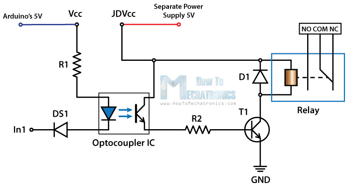
I don't provide Vcc to the optocoupler, but use an 'enable' pin. Also, the idea is to not have a common ground. The relay board and a separate powersupply is of course way more expensive than the bare ATT45 I ended up using instead of an arduino, so if the relay borks and puts 30 VDC (or mains, if you're switching that) on the low voltage side, then it wouldn't matter to much that the Tiny is also fried. Still, especially during prototyping I'd rather keep things optically isolated. Now that it works, and I know the relay doesn't overload the Vcc, I've cheated and use one supply for both relay board and the Tiny.
The relay-controller runs on an ATT45, which talks over (software) serial to a host computer (GLInet router in my case) and from there to the rest of the world. Access control is handled on the host computer, for flexibility and to save space on the ATT45. All output is also rather terse to save space on the ATT45. For the same reason, the code has its static strings broken up into smaller units and I use #defines instead of 'const' variables.
As I was short on pins, I'm using the active low reset pin as an analogue input, making sure not to drop it too low to reset the Tiny. I found I needed a rather big Capacitor to decouple the reset line or when one of the relays switched on, the Tiny would reset due to what I suspect was (E)MI.
/* relay-controller-tiny.ino */

#include <SoftwareSerial.h> // There is no uart on the ATTiny

#define versionstring "TRC1" // Tiny Relay Controller 1.

#define ledPin (0)    // pull low to close the relay controlling the LED lamp
#define doorPin (1)   // pull low to close the relay controlling the door
#define enablePin (2) // High to enable, Low to disable the optocouplers
#define RX (3)  // serial link to host
#define TX (4)  // serial link to host
#define sensorPin (A0) // on reset!
#define rate (19200) // 9600 might be better.

#define crnl "\r\n" // help compiler optimize

bool ansi=false; // there's a bit of color use possible
bool enabled=false; // keeps track of the enable pin being high or low

unsigned char cutoff=244; //cutoff value between open and closed sensor, can be tweaked during runtime
bool sensor=false;  // door open or closed
bool prevsensor=false  // used to detect state changes.

signed char timeout=100;  // watchdog timeout value. note signed char so 127 is max
signed char timer=timeout; // current timer value, if it goes under 0, 'disable' optocouplers.


SoftwareSerial Serial(RX,TX); // control connection to host.

void setup() {
  pinMode(enablePin,OUTPUT);
  digitalWrite(enablePin, LOW); // make sure optocouplers are disabled asap.
  pinMode(doorPin,OUTPUT);
  digitalWrite(doorPin, HIGH); // active low, so enable current can be sunk, to light the led inside opto
  pinMode(ledPin, OUTPUT);
  digitalWrite(ledPin, HIGH); // active low, so enable current can be sunk, to light the led inside opto
  pinMode(sensorPin, INPUT); //will be using this as an analogue input so it can share the reset pin

  enabled=false; // initially we will not be in enable mode
  Serial.begin(rate); //start serial link
  delay(10);
  myversion(); // hello world!
  sensor=(analogRead(sensorPin)/4); // initialize door sensor value
  prompt(); // ready for input
}

void prompt() {
  normal(); // color off
  line(); // new line
  sensor?bred():bblue(); // color bold red when door open, blue when closed
  Serial.write(sensor?"O":"C"); // show O for open, C for closed
  enabled?byellow():bgreen(); // bold yellow when enabled, green when not
  Serial.write(enabled?"# ":"> "); // cisco style prompt to show enabled/disabled
  normal(); // normal color
}

void myversion(){ // simply writes version string to serial line, useful when reconnecting tty
 line();
 Serial.write(versionstring);
}

void pulse(int what,int time){ // pulse a pin for some ms
  digitalWrite(what,LOW);
  delay(time);
  digitalWrite(what,HIGH);
  return;
}
void disable() { // pull enable pin down to de-arm the optocouplers
  if (enabled) { // we call this everytime the watchdog times out, just to be sure, but no need to do feedback when not enabled anyway
    line();
    Serial.write("D");
  }
  digitalWrite(enablePin,LOW); // always call, just to be on the safe side.
  if (enabled) {
    Serial.write("!");
  }
  enabled=false;
}

void enable() { // arms the torpedoes, eh optocouplers by supplying a Vcc
  enabled=true;
  line();
  Serial.write("E");
  digitalWrite(enablePin,HIGH);
  Serial.write("!");
}

void line(){ // newline. might help to make this an inline function or macro instead.
  Serial.write(crnl);
}
// below are some functions to help print out ansi control sequences
void aesc(){ //<esc>[9 leads in all the color sequences
    Serial.write(27);
    Serial.write("[9");
}
void bblack(){
    if (!ansi) return;
    aesc();
    Serial.write("0m");
}
void bred(){
    if (!ansi) return;
    aesc();
    Serial.write("1m");
}
void bgreen(){
    if (!ansi) return;
    aesc();
    Serial.write("2m");
}
void byellow(){
    if (!ansi) return;
    aesc();
    Serial.write("3m");
}
void bblue(){
    if (!ansi) return;
    aesc();
    Serial.write("4m");
}
void bmagenta(){
    if (!ansi) return;
    aesc();
    Serial.write("5m");
}
void bcyan(){
    if (!ansi) return;
    aesc();
    Serial.write("6m");
}
void normal(){
    if (!ansi) return;
    aesc();
    Serial.write(";0m"); // needs the ; so the 9 is not directly prepended
}


void loop() {
    // put your main code here, to run repeatedly:
  char c;
  if (Serial.available()){  // get a character from input if available
    timer=timeout;
    c=Serial.read();
  } else {
    c=' '; // nop command.
  }


  switch (c) { // command dispatcher
    case 'a': //toggle ansi colors
    ansi=ansi?0:1;
    break;
    case 's': //dump current sensor value
    case '=':
      line();
      Serial.write("=");
      Serial.print((analogRead(sensorPin)/4));
      Serial.write("!");
    break;
    case '-': // these adjust the cutoff value to distinguish between open and closed door
    if (enabled) { // need to enable to mess with cutoff values
      cutoff-=2;
    } //fall through, increase by one again, then print new value
    case '+': //increase cutoff (if enabled)
    if (enabled) {
      cutoff++;
      } // fall through, print new value
    case 'c': // dump current cutoff value
    line();
    Serial.write("C");
    Serial.print(cutoff);
    Serial.write("!");
    break;
    case 'd': // disable
    disable();
    break;
    case 'o': // operate door
    Serial.write(crnl);
    Serial.write("O");
    pulse(doorPin,1000); // 1 sec is more than enough, might lower this to save energy ;)
    Serial.write("!");
    break;
    case 'e': // enable - could add a small state machine to read in a kind of secret
    enable(); // but we just trust the upstream access control
    break;
    case 'l': // operates the relay for the led lamp.
    Serial.write(crnl);
    Serial.write("L");
    pulse(ledPin,1000);
    Serial.write("!");
    break;
    case 'v': // print version string again
    myversion();
    break;
    case ' ': // NOP
    // do not do anything if no command received
    break;
    default: // debug by echoing unknown command back; no 'help' screen as takes too much space
    line();
    Serial.write(c);
    Serial.write("?");
    break;
  }

  prevsensor=sensor; // save old sensor value
  sensor=(cutoff<(analogRead(sensorPin)/4)); // closed door, closed reed, pulls down.
  if (sensor!=prevsensor) { // door state changed?
    prompt(); // print a prompt, which will show the changed state
  }

  if (--timer<0) { // decrease watchdog timer
    timer=timeout; // reset  timer
    if (enabled!=0) { // if disabled already then don't spam prompts
      c='~'; //will trigger prompt to show soon to be disabled mode
    }
    disable(); // always call disable, just in case pin glitched on
  } else {
    delay(100); // 100 ms reaction time is fine, timeout=100 units of 100ms this way
  }

  if (c!=' ') { // prompt for new command
    prompt();
  }
}
DONE:
- control typical 'arduino' 2-relay board with NodeMCU.
- control typical 'arduino' 2-relay board with ATTiny 45.
- garage-door opener controller for NodeMCU as PoC - web frontend.
- garage-door opener controller for ATT45, serial 'front'end.
TODO:
- invert logic on door open detection reed contact so open circuit when door closed?
- print a box for mains->USB power brick and connect as separate power supply for coils?
- add more reed contacts at different voltages to detect e.g. fully opened door, or checkpoints along the way. maybe some kind of ultrasound distance meter to detect how far the door is opened?