StofAnanas
| Project StofAnanas | |
|---|---|
| |
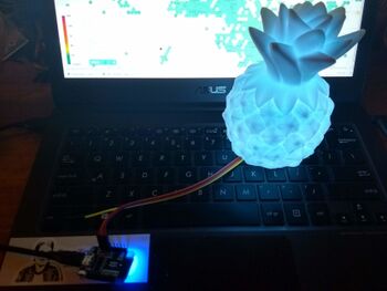
| Showing particulate matter concentration as a coloured light | |
| Status | Completed |
| Contact | bertrik |
| Last Update | 2023-02-01 |
The concept
The stofananas/stoflama visualizes the current airborne particulate matter concentration from the nearest sensor.community measurement station, inspired by http://stoflamp.nl The data that the LED colour is based on is retrieved over WiFi from the stofradar.nl website every 5 minutes.
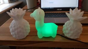
This lamp is a soft plastic translucent pine apple ("ananas") or lama, bought at the "Action" store.
Features:
- The lamp shows particulate matter concentration as a colour, from dark blue for low concentration to bright pink for high concentration
- The lamp retrieves the PM value over wifi from the the stofradar.nl website, there is a one-time setup to configure your WiFi network so the device can access the internet
- The lamp determines its location by based on signal strength and BSSID of nearby WiFi base stations.
- The hardware consists of a Wemos D1 mini board (about E3,-), a LED shield and a USB power supply + cable.
- The software supports two different kinds of Wemos D1 mini LED "shield", both the shield with a single LED and the shield with 7 LEDs arranged in a star.
- Experimental branch retrieves particulate matter data from stofradar.nl, which is more responsive, also includes data from RIVM
Ideas/nice to have/todo:
- some kind of compatibility mode with the stoflamp from stoflamp.nl
- Run the software directly on a WiFi-enabled E14 RGB lamp from the Action store. This lamp has the microcontroller already built in. No separate USB power adapter is needed, it runs directly off 230V. See the WifiLamp project.
- Instead of controlling a light directly, send a command over infrared remote to an RGB lamp already having remote control, see https://www.instructables.com/Reverse-Engineering-RGB-LED-Bulb-with-IR-remote/
Building it
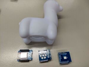
It consists of a few parts:
- a Wemos D1 mini board
- a LED shield, either the one with 1 LED, or the one with 7 LEDs (preferred, brighter)
- a 5V USB charger with stable voltage output + USB cable
- a plastic lamp enclosure
Steps:
- solder the female headers onto the Wemos D1 mini, start with soldering just one pin so you can re-heat it and adjust it if the fit with the male pins is not quite right.
- push the male headers into the female headers and solder the male headers onto the LED shield
- connect the USB micro cable and flash the firmware into the Wemos d1 mini board
- verify that it works as expected, on startup it does a quick colour animation, starting and ending with the red colour
- remove the USB micro cable and push the Wemos d1 mini board + LED shield into the plastic enclosure
- reattach the USB micro cable and verify it still works
It helps to make a few little knife cuts in the plastic of the enclosure to make the wemos d1 mini board fit more easily.
Operation Manual
Flashing the firmware
- Connect everything up as indicated under 'hardware' and connect the Wemos D1 board to the USB port of your development PC / laptop
- Flash the software into the Wemos D1 mini. Open a command line and enter the 'stofananas' source code directory, then compile and upload it using the following command:
pio run -t upload
This assumes you have platformio installed, this is done on Debian Linux for example, as follows:
 sudo apt install python-pip
 sudo pip install platformio
Configuration
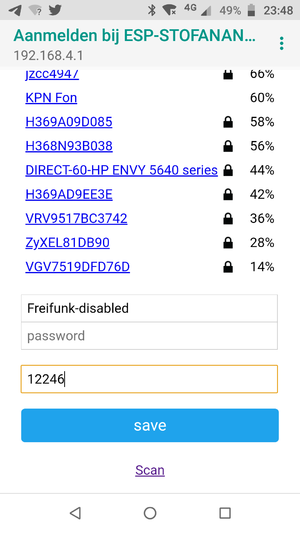
Automatic configuration:
- power up the lamp
- on a mobile phone, connect to the "ESP-PMLAMP" network, and select login
- when presented with the captive portal, select a WiFi network, fill in the WiFi password, press SAVE
Usage
- Power up the lamp while in range of the WiFi network you configured. The LED shows a colour animation when starting up (starting with red and ending with red)
- The LED turns white for a short time, then changes to a colour representing a PM concentration
- A new PM measurement is retrieved automatically every 5 minutes.
- A flashing colour (1x per second) means that something went wrong, either communication with the sensor.community server or decoding the sensor.community server response
Hardware
The electronic part consists of a Wemos D1 mini board and a LED shield.
The LED can be one of these LED shields:
- 1-LED shield: https://wiki.wemos.cc/products:d1_mini_shields:ws2812b_rgb_shield
- 7-LED shield: https://www.wemos.cc/en/latest/d1_mini_shield/rgb_led.html
The 7-LED shield is a lot brighter than the 1-LED shield, I recommend to use the 7-led shield.
Unfortunately not all LED shields are equal, some contain an RGB LED, others have the RGB colours switched. During startup, the colour animation should start and end with the RED colour.
Software
Getting and building the source code
Source code is available on github.
To compile and upload it, I use platform io:
pio run -t upload
The ESP8266 board support should be version 2.6.3!
You can also compile it with the Arduino IDE, libraries used:
- ArduinoJSON (v 6.19.4) for parsing the sensor.community response
- FastLED (v 3.5.0) is used to control the RGB LED
- WiFiManager (v 0.16.0) is used to manage WiFi connection to the local WiFi access point
stofradar.nl interface
The firmware performs a GET on
http://stofradar.nl:9000/air/<latitude>/<longitude>
This returns a JSON message as follows
{"pm2.5":4.25}
Colour mapping
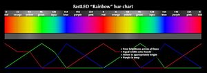
Mapping is currently as follows, using the PM2.5 value:
- 0 ug/m3: deep blue
- 15 ug/m3: green
- 30 ug/m3: yellow
- 60 ug/m3: red
- 120+ ug/m3: pink
This follows roughly a spectral colour scale with continuously varying 'hue', PM-values doubling for each step, with piecewise linear interpolation.
RIVM has an interesting paper on this subject at https://www.rivm.nl/bibliotheek/rapporten/2014-0050.pdf
Chapter 8.3 unfortunately still puts the final colour scale for an air quality index as a point under discussion:
 "Er is overeenstemming over het baseren van de index op dosis-respons
 relaties en het schalen van de componenten naar ordegrootte
 gezondheidseffecten. De analyse die heeft geleid tot een indeling in tien
 klassen is beschreven in hoofdstuk 6. Er is tevens de wens geuit, zowel
 door gebruikers als experts, om in de uiteindelijke presentatie te komen
 tot vier klassen met bijbehorende kleur, labels en handelingsperspectief.
 De precieze afkappunten daarvoor zijn arbitrair. Na de expertbijeenkomst,
 bijeenkomsten met gebruikers en twee commentaarronden onder de experts
 is nog geen consensus over de uiteindelijke indeling van de index in vier klassen.
 De onderstaande indeling (zie Tabel 11) doet zoveel mogelijk recht aan de adviezen van
 de experts en gebruikers, en biedt mogelijkheden om een consistent
 geheel te vormen met de smogregeling. Nog openstaande
 discussiepunten worden hier beschreven."
The https://www.luchtmeetnet.nl/ page uses the following range: https://www.luchtmeetnet.nl/informatie/luchtkwaliteit/luchtkwaliteitsindex-(lki)
Next generation
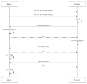
The next generation uses the ESP-NOW protocol, supported by both the ESP8266 and ESP32 microcontrollers. ESP-NOW is a connection-less WiFi protocol running at a reduced rate of 1 Mbps, it does not require any credentials (like WEP/WPA) to be entered. The lamp is *not* connected to regular WiFi, this is different from (say) the mechanism used by the sensor.community flashing tool to find a sensor in the local network.
The idea is that you just put a ESP-now enabled light in the vicinity (several 10s of meters) of the particulate matter sensor and they will automatically discover each others' presence and start communicating measurement values.
Protocol
Pairing works as follows:
- The lamp sends broadcast discovery messages (possibly on different channels) to announce its presence and discover the sensor, it flashes blue while doing so.
- The dust sensor receives the broadcast discovery message and sends an associate message back.
- The lamp receives the associate message, it stops flashing blue.
- The (implicit) ACK from the lamp back to the sensor signals that the association is complete, the sensor remembers the lamp MAC and id
- When a new measurement is done, the sensor sends a data message to the lamp. The lamp shows the associated color.
The data format is JSON, human readable, extensible. Not so friendly on data size, but we can send up to 250 bytes, should be enough. The dust sensor can show in its internal web page that a lamp was found and can display the lamp id.
Example broadcast discovery packet (lamp to dust sensor):
{"msg":"discover","id":"PMLAMP-000D1DD8"}
Example unicast discovery response packet (dust sensor to lamp):
{"msg":"associate","id":"SENSOR-00EE18EC"}
Example unicast measurement/color packet (dust sensor to lamp):
 {"msg":"data","PM10":12.3,"PM2.5":8.4,"PM1.0":4.5,"humidity":42.5,"temperature":14.3,"pressure":102511,"color":"#11FF00"}
 {"msg":"data","color":"#ffff00"}
The lamp software can be implemented to either just display the color, or calculate it from the measurement.
When the sensor does not receive an ACK from the lamp during a number of consecutive transmissions (say 3), it assumes that the lamp is offline and goes back to discovery mode. When the lamp does not receive a message from the sensor during a certain interval (say 300 seconds), it assumes that the sensor is offline and goes back to discovery mode.
Hardware
You need two wemos d1 mini boards, one acting as the 'sensor', the other one as the 'lamp'. The wemos d1 mini acting as 'lamp' should be fitted with an RGB shield.
Software
Source code is available here: https://github.com/bertrik/pmlamp-espnow-proto
Power on the lamp, the LED starts flashing blue, then power on the sensor, the LED stops flashing. You can connect over serial to the sensor node and type a command like 'led FF0000' to set the color of the lamp to red.