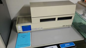
Reflow Oven
Deze reflowoven is niet meer op de space. Werkte niet goed genoeg en nam veel ruimte in. Wie doet 'n voorstel voor een goede vervanging?
| Project Reflow Oven | |
|---|---|

| |
| Status | Completed |
| Contact | Crashjuh |
| Last Update | 2022-05-07 |
Because modern electronics components are tending more and more towards becoming SMD-only, and because the associated size reduction can also be very useful for space projects, we need a reflow oven.
Status
We now have a real reflow oven and currently we are testing what the best settings are. Over time, these data are reported here.
The particular model we have looks like a DIMA SMT Systems SMRO-0170 (to be confirmed). In this document is it referred to as the "Piccolo", with a maximum PCB size of 250x150mm.
Use by Revspace
When you turn it on (switch on the back), it will heat according to the temperatures specified in the currently selected program. Once it's done, you can hit 'start'. The tray will then move all the way to the right (preheat area), wait for a specified period of time, then move to the left (solder area), wait for a period of time, and then finish by moving further to the left (out of the oven). The light will turn on while the tray is inside, so you can check the reflow as it happens.
It makes a lot of noise and produces quite a bit of heat, so probably best to turn on the external extractor fan.
The oven has 10 memory locations (Program number 01 till 10). At the moment we only have programmed program number 01. We program the programs for different PCB thicknesses.
To pick the program: press 'Prog' and use the plus/minus keys to choose a program number, then press 'Prog' again.
To change a program (make sure to CHECK against the settings below): press 'Prog', pick the program number, then use left/right to step through the settings, and plus/minus to change each setting.
The "self-learning" stuff supposedly lets you automatically work out the correct profile with the use of sensors, but we have no documentation and it seems unnecessary.
| Program number | PCB Thickness | |
|---|---|---|
| 01 | 1.5 / 1.6 mm | |
| 02 | xx | |
| 03 | xx | |
| 04 | xx | |
| 05 | xx | |
| 06 | xx | |
| 07 | xx | |
| 08 | xx | |
| 09 | xx | |
| 10 | xx |
- Program number:
Enter : 01
- Preheat standby:
Enter : 080
- Preheat standby:
- Preheat airtemp:
Enter : 150
- Preheat airtemp:
- Preheat time:
Enter : 02:00
- Preheat time:
- Solder temp. :
Enter : 250
- Solder temp. :
- Solder time:
Enter : 01:30
- Solder time:
- Learn preheat:
Enter : 000
- Learn preheat:
- Learn solder:
Enter : 000
- Learn solder:
Gallery
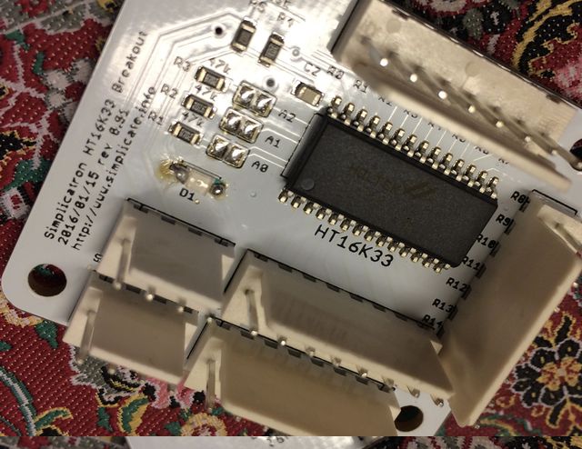
I2C Led driver breakout board, D1 was hand-soldered. Solder paste was applied using a Mylar stencil cut with the revspace lasercutter.
 (Image: robv)