PowerInductorTester
| Project Power Inductor Tester | |
|---|---|

| |
| test inductors to find their saturation current and inductance-current characteristic. | |
| Status | In progress |
| Contact | AlexanderB |
| Last Update | 2022-06-20 |
What
Inductors are often specified with just one inductance figure, but in reality their behaviour is non-linear.
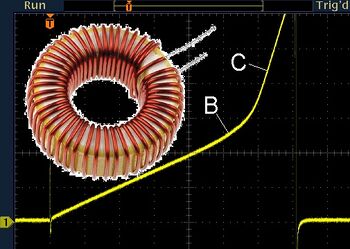
Once an inductor goes into saturation, the inductance decreases quite drastically.
This is especially important for power inductors in DC-DC converters, as going into saturation can lead to magic smoke escaping.
This also makes it possible to test and characterize self-built coils, or coils of unknown origin for which no datasheet exists.
Perhaps not as useful for the people looking to quantize frequency response, but the space has a signal generator for that.
Hardware
The project is based on an existing project that I found here:
https://ludens.cl/Electron/lmeter/lmeter.html
and similar to the one here:
http://elm-chan.org/works/lchk/report.html
I've posed myself the extra challenge of making it fit inside of a peppermint tin.
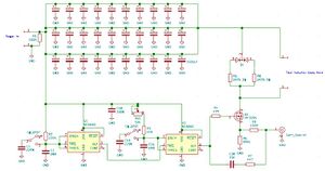
Schematic
And my own version --->

Component Selection
Mostly identical to the original schematic.
Capacitors are 30x 1500uF Low ESR.
A mix of SMD and THT parts to optimize for board space.
PCB
Partly drawn up, I want to verify the components fitting in the enclosure before I finalize the design though.
Usage
Solder the silicone leads to the legs of the inductor under test. This provides lower resistance than connecting with any kind of clamp.
Set the tester to it's lowest setting
Connect the BNC connector to an oscilloscope.
Connect the meter to a lab power supply set to 10 volts, current limited to 1 amp.
Turn up the tester until the saturation point is visible on the scope.
Tiny inductors
Start with the tester pulse time very low, otherwise it's quite possible to blow up very tiny inductors with too strong of a current peak.
Big inductors
The tester should be capable of saturation current of 100A. Higher currents (>60A) may require the power supply be increased to 12V and up to 3A.
This will also overheat the tester, so don't leave it running at 3A.
Math
I refer you back to the original until I write an explanation myself.
https://ludens.cl/Electron/lmeter/lmeter.html
Every millivolt on the scope is 1 amp of current in the inductor.
The slope of the trace can be calculated to the inductance value at that current.
And now?
I'm making two, so I can loan/donate one to the space so others can use it at any time.