Logic probe
| Project Logic Probe | |
|---|---|

| |
| For measurements on digital equipment I could use a logic probe, so I built one | |
| Status | Completed |
| Contact | Mahjongg |
| Last Update | 2017-09-17 |
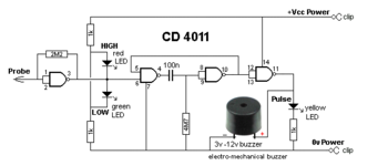
Among other projects my RHOCOCCO project could use one handy measurement device to quickly check digital logic, the digital logic probe. You can buy one, but its much nicer to simply create your own. Its more a mechanical challenge than an electronics challenge, as the electronics consists of little more than a CMOS quad NAND chip a couple of LEDs a capacitor and a few resistors.
For the mechanical design I found a plastic test tube, I glued a steel nail to its point, and fixated the nail further with several layers of heat shrink tube, and by using a stick of hot-glue which tip I melted using hot air I was able to add some hot glue to the bottom of the tube. Obviously beforehand I had soldered a thin wire to the head of the nail, and fixed it with heat shrink tube. It was one wire of a twisted pair, the other wire I intended to ground, so it acted as a bit of shielding to prevent the sensitive wire to pick up mains hum (which was a mistake I later learned). Interestingly the first of the four NANDS is used in analog mode by using a large feedback resistor from output to input, its used as a sensitive pick-up input amplifier.
The probe, after some puzzling, works. Only thing I did not expect is that the input amplifier would turn out unstable, resulting in the continuous burning of the yellow pulse LED. The instability is probably caused by my attempt to more or less shield the input wire causing a parasitic capacitance on the input, resulting in an circuit that has a tendency to oscillate. I think disconnecting that grounded shielding wire will solve the problem.
I had a small speaker in the style of the above picture in the schematic, but I removed it because it had too low an impedance (42 Ohm) and it prevented the yellow pulse LED from lighting up. I think I will replace it with a 3.5mm jack, so I can use it with an earpiece, I will place a few hundred ohms in series with it, to lower the volume, and the load it imposes on the output.
12 september, 2017
I finished the logic probe by removing the "shielding wire", and adding an earpiece connector. it fully works now, it still picks up some noise now, resulting in a slow clicking noise in the earpiece that disappears when you probe either a low or high signal, and the yellow LED then turns off too. Connecting it via some impedance to GND the frequency of the clicks lowers.
I think its a useful test instrument, and I hope I can use it a lot.