Flipdot
| Project FlipDot | |
|---|---|
| |
| Status | In progress |
| Contact | User:Sebastius |
| Last Update | 2019-05-21 |
Status
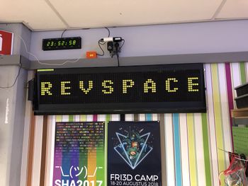
Het bord hangt aan de muur! Te bereiken via MQTT op topic revspace/flipdot
Controller
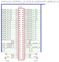
Project op github waarbij een LAWO display wordt aangestuurd door een STM32, met daarin o.a. een pinout van de 50-pins connector met zinnige namen, als ROW_H_0..15, ROW_L_0..15, COL_ADDR_1..4.
Dimensions: 84x16 pixels, distributed over 3 panels of 28x16 pixels each. Each panel has an FP2800 column driver chip.
Interesting links:
- https://c-hack.de/projekte/abgeschlossen/flipdot-hack/
- https://www.fingers-welt.de/wiki/index.php?title=FlipDot
- https://reaktor23.org/projects/flipdot/
50-pin connector
There is a 50-wire cable going from the control board to the actual flipdot-boards. The image on the left shows the pinout of the connector.
This software drives a pixel like this:
- select a row by making one ROW signal high: choose ROW_H_x if you want to set a pixel, or ROW_L_x if you want to clear a pixel. The rest of the ROW_H/ROW_L lines are made low.
- select a column through the COL_ADDR_x pins. The encoding is a bit tricky: a panel of 28 pixels wide has 4 groups of 7 columns each. Pins COL_ADDR_A3/A4 control which group to select, pins COL_ADDR_A0-A2 select (column+1) within the group.
- the polarity of the pixel (set/clear) is encoded on the DATA line
- a strobe (pulse) is sent to one of the panels by toggling one of the Ex lines high then low, to actually update the pixel
It appears that the ROW_H_x/ROW_L_x signals are driven directly at high voltage (18V or so) from the control board, while the COL_ADDR_x signals are at logic level. The FP2800 on the back of each flipdot panel then takes these logic-level signals and turns them into high-voltage (18V or so) column signals.
Probably we can update an entire column at a time, by making several ROW_H_y/ROW_H_y signals high at the same time. Not sure if it is possible to both set and clear pixels in one go, or if it needs two passes: one to set pixels and another to clear pixels.
Driving a pixel
The image above shows an example of how 4 pixels are wired with respect to the ROW_H, ROW_L and column signals.
The logic table describes what happens for combinations of ROW_L(reset), COL and ROW_L(set):
| ROW_L | COL | ROW_H | What happens |
|---|---|---|---|
| 0 | 0 | 0 | - |
| 0 | 0 | 1 | short-circuit from ROW_H to ROW_L! |
| 0 | 1 | 0 | current goes right from COL to ROW_L |
| 0 | 1 | 1 | short-circuit from ROW_H to ROW_L! |
| 1 | 0 | 0 | - (lower diode blocks) |
| 1 | 0 | 1 | current goes left from ROW_H to COL |
| 1 | 1 | 0 | - (upper diode blocks) |
| 1 | 1 | 1 | - |
- we should avoid the short-circuit combinations, where ROW_L is low and ROW_H is high
Serial werkend krijgen
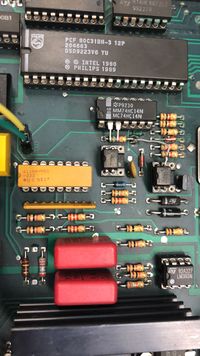
Pin 2 en 3 van de 74HC14 loshalen. Daarna werken de RX en TX pins op het bord met een USB-Serial TTL. GND niet vergeten...
1200Baud, 7E2 (7 bits, Even Parity, 2 Stop bits)
stty -f /dev/ttyUSB0 1200 cs7 parenb -parodd cstopb
STTY blinkt niet uit in duidelijke parameters...
Code
Met dank aan Juerd:
#!/usr/bin/perl -w
use strict;
use autodie;
open my $fh, ">/dev/ttyUSB0";

my $bla = "regel 1\nregel 2";

my $output = "aA11000\n$bla\n\n\r";

my $xor = 0x7f;
$xor ^= ord for split //, $output;

$output .= chr $xor;
syswrite($fh, $output);
MQTT ESP
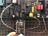
Een NodeMCU hangt aan de serial. Code geschreven in Arduino. Er is een beter printje in bestelling om het netter op te lossen. De secundaire TX pin van de NodeMCU wordt gebruikt (GPIO 15) zodat bij een boot/reboot van de ESP het bord er geen last van heeft.
Reparatie
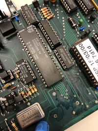
1 IC socket was verteerd door batterijschade. Ook de 4072 vervangen. Kloppen op het IC leverde een reboot namelijk.
Foto's
Characters
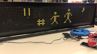
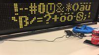
Er zijn diverse characters weer te geven, niet allemaal even logisch.
De characters die leuk worden weergegeven zijn onder andere: "!@#%^&*()_+"
