TIX clock
| Project TIX clock | |
|---|---|
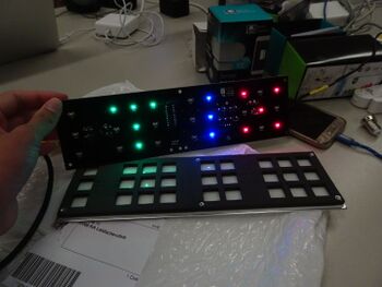
| |
| Status | In progress |
| Contact | Noor, bertrik |
| Last Update | 2020-01-19 |
Have an 'original' TIX clock (YouTube video) from ThinkGeek.
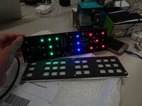
Could also be programmed to display any number up to 4 digits, but the design is best suited for displaying time (blocks are in sets of 3, 9, 6, 9).
Reverse engineering
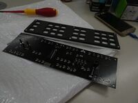
There are a total of 27 LEDs on the board, organised as 9 columns of 3 leds each. Each column has a shared cathode.
There are a total of 19 transistors on the board. Each column has its own transistor.
From left to right:
- column: D27/D18/D9, cathode connected through 62 ohm to collector of Q11, which is controlled through 220 to IC pin 5 (RBx?)
- column: D26/D17/D8, cathode connected through 62 ohm to collector of Q12, which is controlled through 220 to IC pin 6 (RB0)
- column: D25/D16/D7, cathode connected through .. to collector of Q13, which is controlled through ... to IC pin 7 (RB1)
- column: D24/D15/D6, cathode connected through .. to collector of ..., which is controlled through ... to IC pin 9 (RB3)
- column: D23/D14/D5, ... IC pin 10 (RB4)
- column: D22/D13/D4, ... IC pin 11 (RB5)
- column: D21/D12/D3, ... IC pin 12 (RB6)
- column: D20/D11/D2, ... IC pin 13 (RB7)
- column: D19/D10/D1, ... IC pin 15 (RA6)
Rows:
- D27/D26/D25/D19, D24/D23, D22/D21/D20
- D18/D17/D16/D10, D15/D14, D13/D12/D11
- D9/D8/D7/D1, D6/D5, D4/D3/D2
D13 cathode goes to D12 cathode, goes to Q5 collector, Q5 base goes to R5, R5 goes to
Timeline
2019-11
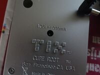
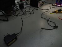
Changed out the American plug for an EU one, but the clock requires 60 Hz AC, and 50 Hz will make it run slow and thus useless for telling time.
2020-01-17 - 2019-01-20
From an old Tweakers thread: "Dus schoef je wekker eens open en google op het typenummer van de chip. 10 tegen 1 dat er een 60/50Hz-select pootje aanzit. Vaak is die verbonden met een draadbruggetje op de print; omsolderen en klaar!"
Looked into this but no luck. Best bet is to replace the chip (original PIC16F628A, with ESP8266?) and update time via wifi.
