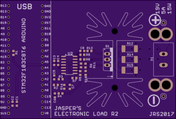
ElectronicLoad
| Project ElectronicLoadV2 | |
|---|---|

| |
| Software voor Electronic Load R2 | |
| Status | Completed |
| Contact | bertrik |
| Last Update | 2018-06-23 |
Intro
Status: the software works! (but there are always more features to add ...)
This page is about software I'm writing for my brother who is developing an 'electronic load'. An electronic load is a thing that draws current from a power source in a well-defined way.
A possible use case for an electronic load is to discharge a battery with a constant current, while recording the voltage so you can make a nice discharge graph.
Another user case is to test a solar panel, drawing variable current from it while measuring the voltage, to find the point where it delivers most power.
Perhaps yet another use case is just to measure current drawn by a specific device at a high time resolution, and determine the amount of charge used per use cycle.
Design
Hardware
For the hardware design, see https://www.tindie.com/products/jaspersikken/jaspers-electronic-load-r2/
The basic principle of operation is that the electronic load has a circuit with a mosfet controlled by a microcontroller to draw a configurable constant current. The mosfet is attached to a heatsink that dissipates the power as heat.
The microcontroller can set the desired current, measure the actual current and measure the voltage. This way we can also do other modes than just constant current:
- constant power mode: from the voltage measured, we can calculate the current required to draw a constant power
- constant resistance mode: from the voltage measured, we can calculate the current to emulate a specific resistance
Software
Building blocks:
- USB serial port, to receive commands from the user
- command interpreter, to transform user input into actions
- measurement loop, that continuously calculates voltage and current, and integrates them (from mA to mAh for example)
- control loop, that maintains the desired behaviour (constant current, power, resistance)
- logging logic, to log measured values to the output
- sequencing logic, to perform the steps needed for particular measurement mode, e.g. solar panel characterisation
Random thoughts
Features to implement:
- sequencer for stepping through a specific range of currents at a specific speed
- operating modes:
- add sequenced modes: special sequences for measuring a PV-cell, measuring a battery, measuring a Peltier?
- automatic max power point determination?
- calibration
- automatic if possible, e.g. set current to 0, measure current, use this as an offset?
- manual if required
- save calibration values in non-volatile memory and load them at startup
- automatically reset cumulative counters when starting a log
- conversion from SI units to other units, like mAh, Wh, etc?
Platform IO
platformio is a kind of build environment. It takes out the guesswork/manual steps of using the Arduino environment to pick the right board, libraries and options. All of this can now be specified in text files (e.g. platformio.ini) and separately per individual project.
Installation
First you need to install pip, e.g. for debian Linux:
sudo apt-get install python-pip
Then you can use pip to install platformio
sudo pip install platformio
Also make sure you install and activate the udev-rules, according to the platformio-udev-rules description on the platformio page.
Platformio commands
Just 'cd' into the directory containing the platformio.ini file. Platformio will automatically download and cache any requirements (like dependent libraries, tool chains, upload utilities, etc). Instead of typing platformio you can just type pio.
To just compile the software and download dependencies:
pio run
To compile and upload the firmware:
pio run --target upload
To run the serial monitor:
pio run --target monitor
or
pio device monitor