MainsFrequency
| Project MainsFrequency | |
|---|---|
| File:Whyunoimage.jpg | |
| A simple mains frequency counter | |
| Status | Initializing |
| Contact | bertrik |
| Last Update | 2018-04-22 |
Introduction
This page is about creating a simple frequency counter for mains power and publish the frequency over MQTT.
It's based on the Arduino platform, using an ESP8266 to do the wifi/network/MQTT stuff.
The frequency measurement principle is to count the number of mains cycles in a fixed period. To get a resolution of 0.01 Hz, the period is 100 seconds.
To keep the measurement circuit relatively safe, only a small part of the electronics is actually connected to mains.
Hardware
The plan is to use an ESP8266 because it can easily publish the measured value over wifi/MQTT.
I'm looking at various ways of actually getting the mains signal into the microcontroller. The simplest way appears to be an optocoupler in series with R, C and a diode anti-parallel over the optocoupler's LED.
- could be a transformer, like shown here. Safe but bulky.
- could be a capacitive/resistive dropper with an optocoupler, like the circuit in this post (note: this circuit is for 120V!)
- could be this thing from aliexpress
Aliexpress circuit

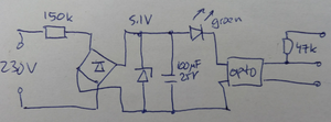
The circuit as reverse engineered is shown on the right. Basically, the mains is rectified through a high-value high-power resistor and a bridge rectifier, then stabilized with a zener to 5.1V, which lights the green LED and activates the optocoupler to pull the output low when mains is present. The 47k pull-up makes the signal high when there is no mains power available.
So this circuit doesn't actually do what I want: the opto is activated all the time when 230V is present, it's not flashing at 50 Hz.
Circuit

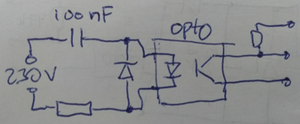
The circuit on the right is the one I plan to use.
The capacitor drops most of the voltage. It should be an x-rated type, you can tell by the marking "X2". The resistor (1k or so) limits the inrush current. The diode (1N4148 probably) protects the optocoupler (4N27 or 4N35) from reverse voltage. The resistor on the right is a pull-up resistor, possibly not even needed if I use the built-in pull-up of the microcontroller.
At 50 Hz, the capacitor has a reactance of about 32 kOhm, so the LED current should be something like 230V/32kOhm = 7 mA, well below the maximum of 60 mA mentioned in the data sheet. Possibly, a bleeder resistor could be put parallel to the capacitor, to make sure that the capacitor doesn't stay charged when the circuit is powered off. Power consumed in the resistor is R*I*I so about 50 mW, so we can probably use the very common 250 mW type there.
Software
See the github page.
The working principle is that we count the number of cycles in a 100 second period, this should nominally be 5000. A cycle count is done every second and the result is put in a circular buffer of 100 bins. The average of these 100 bins then provides the frequency over the past 100 seconds.
The accuracy of the frequency count depends on the accuracy of the crystal (among other things). To get 0.01 Hz error at 50 Hz, we need an time reference with at most 0.01 / 50 = 200 ppm frequency deviation. This is probably doable with the built-in crystal on a typical ESP8266 board (like a Wemos D1 mini).