Lange lichtkrant: Difference between revisions
mNo edit summary |
|||
| Line 3: | Line 3: | ||
|Picture= | |Picture= | ||
|Omschrijving= | |Omschrijving= | ||
|Status= | |Status=Abandoned | ||
|Contact=Sebastius | |Contact=Sebastius | ||
|Contact1=Maxell | |Contact1=Maxell | ||
Latest revision as of 22:08, 29 May 2024
| Project Lange Lichtkrant | |
|---|---|
| Status | Abandoned |
| Contact | Sebastius, Maxell |
| Last Update | 2024-05-29 |
Sebastius vond zomaar ergens een hele lange ledbanner. 7 meter lang, 1 regel hoog. Deze is inmiddels (op 29 november 2016) aangeschaft voor 150 euro. Helaas was de behuizing uit één stuk en kon deze niet mee. We hebben de diffusers, ledboards, controller, voedingen en bekabeling.
What
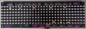
It's a long LED banner, 7 pixels high, very long.
Parts:
20x Ledboard (ca 34,5cm lang per stuk), 5 karakters per bordje
 1x Controllerboard
 2x 5v 20A voeding
 2x Kabelboom 5v
 1x Ethernet - Serial brug (Lantronix UDS1100)
 1x Serial kabel
 4x CDRom met software (Twee CD's hebben de installer van het lichtkrant-programeertooltje (MLN v2.20), verder een Cd met driver en CD met quick guide van de UDS1100 (met papieren boekje!)).
 1x Handleiding
Next steps:
- further reverse engineering of the display panels, e.g.
- figure out how the shift registers are clocked
- figure out how the data registers are connected
- control one board to help understand how it works
Where
Momenteel is dit project opgeruimd, ingepakt in een SAMLA in de lounge. De diffusers liggen in de lounge achter de bank.
Reverse engineering

Each panel is 30 pixels wide, 7 pixels high.
Parts:
- 2x74HC245 (U1/U2): 8-bit bus transceiver with 3-state output
- 5x74HC595 (U3 and U4/U5/U6/U7): 8-bit serial shift register
- 1x74HC164 (U8): 8-bit serial-in, parallel-out shift register
- 2xSTA402A: quad PNP darlington
Power is supplied separately from the 12-pin connector, left of the twin darlingon chips.
Connector (top right):
- 1: GND
- 2: pin U2.B0
- 3: pin U2.B5
- 4: jumper between U2 and U3
- 5: ?
- 6: pin U2.B2
- 7: pin U2.B3
- 8: pin U1.OE
- 9: pin U2.B4
- 10: GND
- 11: ?
- 12: ?
The STA402A transistor base inputs are fed through the set of 7 resistors just left of U3 (595), very likely the row inputs.
The panel has three identical connectors of 12 pins each (they are not electrically identical).
Theory of operation
Possibly the column data is contained in the top chain of 4x74HC595 on top of the board. There are 30 resistors there also, exactly the number of columns.
Actuation of a row is probably done by the drivers inside the twin STA402A. The 595 probably acts as the row selection registers, the twin 245's acting as buffer and twin STA402A's as driver.
It is not completely clear what the 1x74HC164 does.
Foto's
Donaties
Er is meer gedoneerd dan verbruikt. De resterende 50 euro wordt gebruikt om materialen ter montage aan te schaffen.
| Naam/Nick | Bedrag | Betaald? |
|---|---|---|
| Juerd | 25 | Ja, Gebunqerd. |
| flok420 | 5 | Ja, revbank |
| Peetz0r | 25 | Ja, revbank |
| Sebastius | 40 | - |
| Jelle | 10 | Ja, revbank |
| Maxell | 20 | Ja, contant aan Sebastius |
| Crashjuh | 10 | Ja, revbank |
| CFW | 10 | Ja, via RevBank aan Sebastius |
| HansG | 10 | Ja, contant aan Sebastius |
| Smeding | 10 | Ja, revbank |
| merethan | 25 | Ja, revbank |
| Luteijn | 10 | Ja, contant aan Sebastius |

