CJMCU-811: Difference between revisions
From RevSpace
No edit summary |
No edit summary |
||
| Line 8: | Line 8: | ||
== Introduction == | == Introduction == | ||
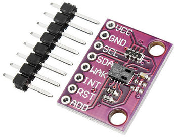
I bought this | I bought this board from Aliexpress, it's a breakout board for [https://ams.com/ccs811 the AMS CCS-811]. | ||
The CCS-811 is an ultra-low power digital gas sensor for monitoring indoor air quality. | |||
The | The datasheet can be found [https://ams.com/ccs811#tab/documents here]. | ||
Pins: | == Hardware == | ||
* VCC connect this to 3.3V | Pins on the breakout board: | ||
* VCC this is directly connected to the IC (there is no voltage regulator on board), connect this to 3.3V | |||
* GND to ground obviously | * GND to ground obviously | ||
* SCL | * SCL signal from I2C | ||
* SDA | * SDA signal from I2C | ||
* WAK this needs to be low (!) in order for the chip to be active | * WAK this needs to be low (!) in order for the chip to be active | ||
* INT can be left unconnected | * INT can be left unconnected | ||
* RST can be left unconnected | * RST can be left unconnected | ||
* ADD can be left unconnected | * ADD can be left unconnected (?) | ||
My board was apparently configured at I2C address 0x5A. | My board was apparently configured at I2C address 0x5A. | ||
I'm wiring it up to a Wemos D1 mini board with an ESP8266. | |||
== Software == | |||
I found two libraries: | |||
* [https://github.com/adafruit/Adafruit_CCS811 Adafruit CCS811 Library] | |||
* [https://github.com/sparkfun/SparkFun_CCS811_Arduino_Library SparkFun CCS811 Arduino Library] | |||
Revision as of 09:37, 30 December 2018
| Project CJMCU-811 | |
|---|---|

| |
| Playing around with a breakout board for the CSS-811 IC | |
| Status | Initializing |
| Contact | bertrik |
| Last Update | 2018-12-30 |
Introduction
I bought this board from Aliexpress, it's a breakout board for the AMS CCS-811. The CCS-811 is an ultra-low power digital gas sensor for monitoring indoor air quality.
The datasheet can be found here.
Hardware
Pins on the breakout board:
- VCC this is directly connected to the IC (there is no voltage regulator on board), connect this to 3.3V
- GND to ground obviously
- SCL signal from I2C
- SDA signal from I2C
- WAK this needs to be low (!) in order for the chip to be active
- INT can be left unconnected
- RST can be left unconnected
- ADD can be left unconnected (?)
My board was apparently configured at I2C address 0x5A. I'm wiring it up to a Wemos D1 mini board with an ESP8266.
Software
I found two libraries: