MainsFrequency: Difference between revisions
m →Reboot |
|||
| Line 46: | Line 46: | ||
For measurement with an ESP8266, like a Wemos or nodemcu, you need to put about 180k ohm resistor in line with the output from the ZMPT101B to the A0 input. | For measurement with an ESP8266, like a Wemos or nodemcu, you need to put about 180k ohm resistor in line with the output from the ZMPT101B to the A0 input. | ||
The A0 input already has a 220k/100l resistive divider, effectively becoming a 400k/100k resistive divider with the series resistor, scaling down the 0-5V | The A0 input already has a 220k/100l resistive divider, effectively becoming a 400k/100k resistive divider with the series resistor, scaling down the 0-5V range to the 0-1V range required for the ESP8266. | ||
The "blue pill" seems to have too low accuracy of the built-in crystal, about 100 ppm, while we need about 20 ppm to get 1 mHz resolution. Notes about blue pill crystal accuracy: | The "blue pill" seems to have too low accuracy of the built-in crystal, about 100 ppm, while we need about 20 ppm to get 1 mHz resolution. Notes about blue pill crystal accuracy: | ||
Revision as of 09:25, 16 March 2023
| Project MainsFrequency | |
|---|---|

| |
| A simple mains frequency counter | |
| Status | Completed |
| Contact | bertrik, Peetz0r |
| Last Update | 2023-03-16 |
Introduction
This page is about a simple circuit for measuring the frequency of grid power, publishing it over MQTT.
It's based on the Arduino platform, using an ESP8266 to do the wifi/network/MQTT stuff. The frequency measurement principle is to count the number of mains cycles in a fixed period. To get a resolution of 0.01 Hz, we count for approximately 5000 cycles at 100 Hz, so the period is 50 seconds. To keep the measurement circuit relatively safe, only a part of the electronics is actually connected to mains and the low-voltage side is isolated with an optocoupler.
Reboot
Instead of just counting pulses from zero-crossings, we could sample the actual 50 Hz waveform and do autocorrelation, an FFT (or similar) for example.
Perhaps get the following stuff out of it:
- get more accurate frequency measurement
- get more responsive frequency measurement, i.e. instantaneous value, not a running average over 50 seconds.
- determine "purity" of the waveform, i.e. how much it deviates from a pure sine wave
A suitable module for relatively safely sampling the mains voltage could be this ZMPT101B module. It contains a transformer and an op-amp circuit.
More information about this module:
Proposed algorithm for getting accurate instantaneous frequency out of it:
- Sample the mains frequency waveform during approximately one second (say 5 - 10 kHz)
- Determine the median, lower and upper quartiles of the waveform, and shift data so its values are symmetrically around zero
- Calculate zero crossings by doing linear regression to find the zero-crossing of the wave in the region around the zero crossing (in between the quartile values), this gives sub-sample time resolution
- The linear regression can be run as a kind of state machine, just keeping track of sum(x), sum(y), sum(x*x), sum(x*y) is enough to perform a linear regression at any time
- Do this over the approximately 50 cycles contained in the one second data and determine average frequency
-> this should give about 1 millihertz frequency resolution in one second
Github project: https://github.com/bertrik/MainsFrequency
For measurement with an ESP8266, like a Wemos or nodemcu, you need to put about 180k ohm resistor in line with the output from the ZMPT101B to the A0 input. The A0 input already has a 220k/100l resistive divider, effectively becoming a 400k/100k resistive divider with the series resistor, scaling down the 0-5V range to the 0-1V range required for the ESP8266.
The "blue pill" seems to have too low accuracy of the built-in crystal, about 100 ppm, while we need about 20 ppm to get 1 mHz resolution. Notes about blue pill crystal accuracy: https://sparklogic.ru/arduino-for-stm32/accurate-blue-pill-clock-frequency-adjustment.html
Status

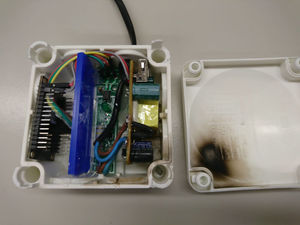
It works! It blew itself up after being moved to a different casing, but was fixed!
See Live view of the AC main frequency as measured at RevSpace
Compare it with:
- Swiss grid frequency graph
- mains frequency. NOTE: don't leave this site open for too long, it'll ban your IP for 'traffic exceeded' reasons!
Possible future enhancements:
- Display the frequency on a nice little OLED screen (or something similar)
Hardware


The microcontroller is an ESP8266 because it can easily publish the measured value over wifi/MQTT.
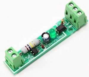
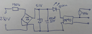
The circuit to sense the frequency is this mains module sold on Aliexpress, with a small modification. The modification is that the smoothing capacitor has been removed, resulting in a 100 Hz signal going into the optocoupler (a pulse during each zero crossing).
How things are wired:
- Used the modified Aliexpress circuit.
- Used a nodemcu v3 for the ESP8266 (this was what was available at the hacker space)
- Mains power going into the mains detection module (left part of the schematic)
- ESP8266 pin 3.3V: connected to the pull-up on the mains module output (top in schematic - green wire)
- ESP8266 pin D5: connected to the optocoupler output on the mains module output (middle in schematic - brown wire)
- ESP8266 pin GND: connected to the GND pin on the mains module output (bottom in schematic - yellow wire)
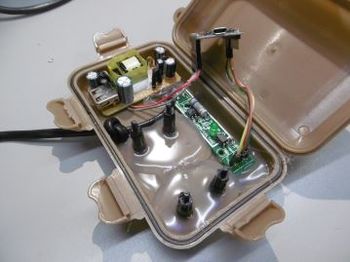
- put in a plastic enclosure with warning labels
Software
The Arduino source is available on the github page.
An interrupt is generated for each falling edge of the signal coming out of the optocoupler. This happens during the zero crossing, so twice each mains cycle, 100 times per second. The working principle is that we count the number of interrupts in the past 50 second period, this should nominally be 5000. An interrupt count is done every second and the result is put in a circular buffer of 50 bins (one for each second). The sum of these 50 bins divided by 100 then provides the average frequency over the past 50 seconds.
A simple filter suppresses spurious pulses: when an interrupt occurs, the counter is increased only when more than 8 ms has passed since the previous zero crossing. Without this filter, the frequency was typically about 2 Hz too high.
The accuracy of the frequency count depends on the accuracy of the crystal (among other things). To get 0.01 Hz error at 50 Hz, we need a time reference with at most 0.01 / 50 = 200 ppm frequency deviation. This is doable with the crystal on a typical ESP8266 board (which has an accuracy of 25 ppm or so).
You can build the software with platformio ('pio run'), it uses libraries WifiManager and PubSubClient.
References
Other interesting projects/documents:
- https://oinkzwurgl.org/projaeggd/mains-frequency/
- http://www.palebluedot.nl/jml/projects/arduino/43-measure-mains-power-frequency
- https://engmousaalkaabi.blogspot.nl/2016/11/ac-220v-frequency-counter-using-arduino.html
- Interesting App Note by Microchip about capacitive droppers
- https://a01.veron.nl/download/hamnieuws/2016/Ham-06-2016.pdf (see page 20, 220nf, 2M Ohm bleeder)
