VINDRIKTNING: Difference between revisions
| Line 40: | Line 40: | ||
== Hacking == | == Hacking == | ||
The microcontroller is an ES7P001. | The microcontroller is an ES7P001. | ||
Idea: Fit an ESP8266 that reads out the raw PM value and publish it over WiFi, e.g. using a home assistant compatible protocol. | Idea: Fit an ESP8266 that reads out the raw PM value and publish it over WiFi, e.g. using a home assistant compatible protocol. | ||
Revision as of 23:25, 31 August 2021
| Project VINDRIKTNING | |
|---|---|

| |
| Hacking IKEA VINDRIKTNING PM2.5 indicator | |
| Status | In progress |
| Contact | bertrik |
| Last Update | 2021-08-31 |
What
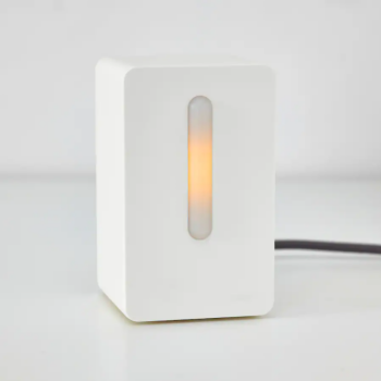
This page is about hacking the IKEA VINDRIKTNING PM2.5 indicator light.
Hardware
- power is by USB-C probably 5V
- the particulate matter sensor is the PM1006, probably very similar to the Cubic PM1006K but with a slightly different command set
- has LEDs for three colours (red, orange and green)
- has a light level sensor
- the sensor output can be PWM or UART, the UART output provides a PM2.5 value
Pictures of its internals: https://twitter.com/guido_burger/status/1413900622919872521
- there is a footprint for a kind of debug header, with signals ISPDA, RESET, ISPCLK, GND, +5V
- there is an internal header with signals LED_G_1, PWM_Fan, LED_R_1, FAN-, FAN+
- there is a separate header for the fan with signals FAN+,FAN-
- there is an 8-pin IC, could this be the "main" microcontroller?
- there is a light-sensing element, that controls the brightness of the LED
More pictures of its internals, with reverse-engineered schematics: https://threadreaderapp.com/thread/1415291684569632768.html
VINDRIKTNING Schematic by Adam Hořčica
NOTE: the schematic appears to swap pin 2 and 4 which connect the GND and +5V!!!
Interfacing with ESP8266
The datasheet of the PM1006 mentions that it takes 5V as power and communicates using 4.5V levels. The reverse-engineered schematic shows resistors in line with the RX and TX lines. An ESP8266 should be 5V tolerant. This means that it is probably possible to directly connect an ESP8266 in place of the original microcontroller.
The series resistors limits the current from the PM1006 TX line into the ESP8266 RX line.
Hacking
The microcontroller is an ES7P001.
Idea: Fit an ESP8266 that reads out the raw PM value and publish it over WiFi, e.g. using a home assistant compatible protocol.
With no PM1006 attached at all, the sensor indicates "green", or good air quality!
What I've done:
- Remove the existing microcontroller entirely
- Solder wires to the internal test pads and attach a Wemos D1 mini, the serial line resistors currently in place can be of use to limit 5V/3.3V interface issues.
Pinout:
- Wemos D1 mini D2 -> PM1006 RX = "ISPDA" pad
- Wemos D1 mini D1 -> PM1006 TX = "RESET" pad
- Wemos D1 mini A0 -> VINDRIKTNING LDR = "LED_R1" pad
- Wemos D1 mini D0 -> VINDRIKTNING FAN control = "PWM_FAN" pad
- Wemos D1 mini D5 -> VINDRIKTNING green LED = LED_G1" pad
- Wemos D1 mini D3 -> VINDRIKTNING red/orange LED = "ISPCLK" pad
Unfortunately, the ESP8266 output voltage is not enough to light the orange LED. It can only control the red LEDs and the green LEDs.
Protocol
Mentioned here, the MCU sends
11 02 0B 01 E1
This is different from the command mentioned in the PM1006K data sheet!
Someone told me:
- The PM1006K "PM" command results in the same PM2.5 value as the PM1006 "PM2.5" command, the PM1.0 and PM10 values will be 0 in the response
Software
Some intial, untested code for an ESP8266 (Wemos D1 mini) to communicate with the PM1006 sensor inside this device can be found at https://github.com/bertrik/pm1006
The hardware probably needs a level shifter in line with the RX and TX signals.