Intakefancontroller: Difference between revisions
mNo edit summary |
|||
| Line 24: | Line 24: | ||
== Status == | == Status == | ||
It works fine as-is, but apart from the addition of some shiny baubles (in the form of sebastius' rgb | It works fine as-is, but apart from the addition of some shiny baubles (in the form of sebastius' rgb knopjes) I do still have to improve the cable management situation. Also, opening it up is a bit of a pain at the moment, because the buttons on the front lid are hardwired to the pcb (which is itself mounted in a case that is firmly screwed to the wall). The upgraded buttons will get a connector. | ||
== Help, it isn't working! == | == Help, it isn't working! == | ||
Revision as of 14:56, 8 January 2019
| Project Intake Fan Controller | |
|---|---|

| |
| Simple fan controller for switching our forced air intake. | |
| Status | In progress |
| Contact | thomas |
| Last Update | 2019-01-08 |
Why
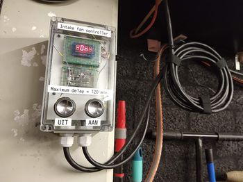
Sometimes the need arises to temporarily shut off our forced air intake fan. In the past we simply pulled the plug on the motor, but this naturally leads to people forgetting all about it until someone notices notices an uptick in CO2 concentration, often days later. This box of plastic is meant to remedy that problem. Pressing a button will shut off the fan and set a counter. Another press will add more time to the counter. Once the countdown completes it will simply start the fan back up, no fuss.
How
To turn the fan off, press the button labeled 'UIT'. Upon first press it will set a delay of 15 minutes, and each successive press adds another 15 minutes to the clock (up to a maximum off-time of 2 hours).
If you want to reset the timer and/or turn the fan back on before the delay has elapsed, just press the 'AAN' button.
What's in the box
An arduino nano reads the buttons, drives the display, and switches a bistable relay. It also pulls a pin high when the fan is on, which is routed to a nodemcu used for interfacing with revspace MQTT (work in progress).
Status
It works fine as-is, but apart from the addition of some shiny baubles (in the form of sebastius' rgb knopjes) I do still have to improve the cable management situation. Also, opening it up is a bit of a pain at the moment, because the buttons on the front lid are hardwired to the pcb (which is itself mounted in a case that is firmly screwed to the wall). The upgraded buttons will get a connector.
Help, it isn't working!
If the buttons are unresponsive, I suggest turning the controller off and then on again. You will find a switch on the top side, it controls the 5v supply to the arduino/esp. If that doesn't work, I suggest throwing your hands in the air and walking away quietly. Someone will report it, i'm sure.
Want to help?
If you want to help and/or add functionality, let me know. I can give you the OTA password for the ESP and show you how to take it off the wall without breaking something.