EncodingLora: Difference between revisions
No edit summary |
No edit summary |
||
| (11 intermediate revisions by the same user not shown) | |||
| Line 1: | Line 1: | ||
{{Project | {{Project | ||
| Name=EncodingLora | | Name=EncodingLora | ||
| Status= | | Status=Stalled | ||
| Contact=bertrik | | Contact=bertrik | ||
| Picture=DecodingLora_Project.jpg | | Picture=DecodingLora_Project.jpg | ||
| Line 13: | Line 13: | ||
* we're creating a stereo WAV-file that represents the I and Q components of the complex baseband radio signal. | * we're creating a stereo WAV-file that represents the I and Q components of the complex baseband radio signal. | ||
* this WAV-file should have the right properties for being played back in GnuRadio using Tx-capable SDR like the Ettus B210, HackRF or the Rad1o | * this WAV-file should have the right properties for being played back in GnuRadio using Tx-capable SDR like the Ettus B210, HackRF or the Rad1o | ||
* initially the focus is on just generating a "LoRa-like" signal, consisting of a valid preamble (with sync pattern) but with pseudo-random | * initially the focus is on just generating a "LoRa-like" signal, consisting of a valid preamble (with sync pattern) but with pseudo-random data after the header. This should be good enough to be used as an interference signal in studies about the robustness against interference from other LoRa devices. | ||
* later when I understand the packet structure better, I can replace the pseudo-random data by actual channel coded data | |||
* I'm planning this as a signal processing chain consisting of several blocks in series, very much how GnuRadio works. I'll probably be writing this in C or Java because these are the languages I'm most familiar with. Maybe later I can port this to the GnuRadio framework. | * I'm planning this as a signal processing chain consisting of several blocks in series, very much how GnuRadio works. I'll probably be writing this in C or Java because these are the languages I'm most familiar with. Maybe later I can port this to the GnuRadio framework. | ||
Next steps: | Next steps: | ||
* | * I forgot about the 1/4th symbol at the end of the preamble, I'll add that and clarify some names in the source code. | ||
* play back the WAV file on an SDR and verify the generated waveform to validate the principle. | * implement DE parameter (if enabled, difference in shifts between symbols is bigger, making it more robust but a bit slower). | ||
* play back the WAV file on an SDR and verify the generated waveform to validate the principle, e.g. check if the carrier detect indication of the receiver triggers on my signal | |||
* do more research on the channel coding, make it work for a very simple set of parameters, e.g. SF=10,DE=1,CR=4/8, which means 8bits/symbol, or 2 symbols per input byte. | |||
== Signal structure == | |||
How I plan to generate to synthesize the signal, is as an over-sampled sweep, offset in base-band frequency so that it does not sweep through or near 0 Hz. | |||
This should make it easier to deal with DC offset problems and mirror images when it is finally up-converted from base-band to RF in the SDR. | |||
I plan to choose the sampling frequency as some nice integer multiple of the bandwidth (power-of-two even). | |||
== Software == | |||
Some initial code can be found here: https://github.com/bertrik/lorasyn | |||
It creates a raw data file with a preamble consisting of 8 unmodulated symbols, a sync word, two reverse chirps followed by 16 symbols of random data. | |||
The I and Q samples are encoded as signed 8-bit words and interleaved (even = I, odd = Q). | |||
The example code uses a BW parameter of 125 kHz, the sample rate is chosen exactly 8 times higher at 1 MHz. | |||
The signal frequency is offset so it is centered around Fs/4, or 250 kHz. | |||
When transmitting the signal through an SDR, the SDR mixer frequency should therefore be tuned 250 kHz lower than the desired LoRa center frequency. | |||
[[File:audacity_import_raw.png|thumb|right]] | |||
You can read this into Audacity (using it as a poor man's signal analyzer), by importing the signal in raw format and using the settings as shown on the right. | |||
[[File:audacity_syn1.png|thumb|left]] | |||
In spectrogram view it looks like this: | |||
* in yellow, the 8 unmodulated preamble symbols | |||
* in green, the 2 sync symbols | |||
* in red, the 2 reverse symbols | |||
* in blue, the 16 random data symbols | |||
There are two identically looking signals in the spectrogram view, these are the I and Q signals, but you cannot really see any difference between them in this view. | |||
Latest revision as of 13:17, 11 May 2020
| Project EncodingLora | |
|---|---|

| |
| Status | Stalled |
| Contact | bertrik |
| Last Update | 2020-05-11 |
This page is about synthesizing a LoRa signal such that it can be "played" back using a software-defined-radio with transmit-capabilities. This should help further in understanding the structure of the LoRa modulation, see also my other page DecodingLora. The desired end result is that the transmitted LoRa signal is compatible with and can be received with existing LoRa hardware.
Basic ideas:
- we're creating a stereo WAV-file that represents the I and Q components of the complex baseband radio signal.
- this WAV-file should have the right properties for being played back in GnuRadio using Tx-capable SDR like the Ettus B210, HackRF or the Rad1o
- initially the focus is on just generating a "LoRa-like" signal, consisting of a valid preamble (with sync pattern) but with pseudo-random data after the header. This should be good enough to be used as an interference signal in studies about the robustness against interference from other LoRa devices.
- later when I understand the packet structure better, I can replace the pseudo-random data by actual channel coded data
- I'm planning this as a signal processing chain consisting of several blocks in series, very much how GnuRadio works. I'll probably be writing this in C or Java because these are the languages I'm most familiar with. Maybe later I can port this to the GnuRadio framework.
Next steps:
- I forgot about the 1/4th symbol at the end of the preamble, I'll add that and clarify some names in the source code.
- implement DE parameter (if enabled, difference in shifts between symbols is bigger, making it more robust but a bit slower).
- play back the WAV file on an SDR and verify the generated waveform to validate the principle, e.g. check if the carrier detect indication of the receiver triggers on my signal
- do more research on the channel coding, make it work for a very simple set of parameters, e.g. SF=10,DE=1,CR=4/8, which means 8bits/symbol, or 2 symbols per input byte.
Signal structure
How I plan to generate to synthesize the signal, is as an over-sampled sweep, offset in base-band frequency so that it does not sweep through or near 0 Hz. This should make it easier to deal with DC offset problems and mirror images when it is finally up-converted from base-band to RF in the SDR. I plan to choose the sampling frequency as some nice integer multiple of the bandwidth (power-of-two even).
Software
Some initial code can be found here: https://github.com/bertrik/lorasyn
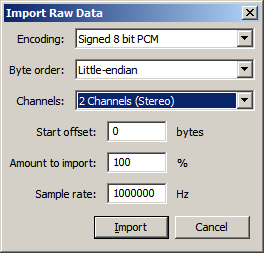
It creates a raw data file with a preamble consisting of 8 unmodulated symbols, a sync word, two reverse chirps followed by 16 symbols of random data. The I and Q samples are encoded as signed 8-bit words and interleaved (even = I, odd = Q). The example code uses a BW parameter of 125 kHz, the sample rate is chosen exactly 8 times higher at 1 MHz. The signal frequency is offset so it is centered around Fs/4, or 250 kHz. When transmitting the signal through an SDR, the SDR mixer frequency should therefore be tuned 250 kHz lower than the desired LoRa center frequency.

You can read this into Audacity (using it as a poor man's signal analyzer), by importing the signal in raw format and using the settings as shown on the right.

In spectrogram view it looks like this:
- in yellow, the 8 unmodulated preamble symbols
- in green, the 2 sync symbols
- in red, the 2 reverse symbols
- in blue, the 16 random data symbols
There are two identically looking signals in the spectrogram view, these are the I and Q signals, but you cannot really see any difference between them in this view.