GL-iNet: Difference between revisions
| (14 intermediate revisions by 3 users not shown) | |||
| Line 1: | Line 1: | ||
{{Project | {{Project | ||
|Name=GL- | |Name=GL-iNet | ||
|Status= | |Status=Completed | ||
|Contact=User:FooBar | |Contact=User:FooBar | ||
|Picture=Gl-inet.png | |||
}} | }} | ||
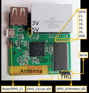
[[File:Glinet-pinout.png|thumb|right|GL- | [[File:Glinet-pinout.png|thumb|right|GL-iNet Pinout]] | ||
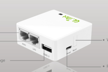
[[File:Gl-inet.png|thumb|right|GL- | [[File:Gl-inet.png|thumb|right|GL-iNet]] | ||
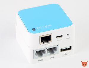
[[File:GLiNet_07_1200_tech-blog.jpg|thumb|right|GL- | [[File:GLiNet_07_1200_tech-blog.jpg|thumb|right|GL-iNet vs TP WR-703]] | ||
== High Res Board Images == | == High Res Board Images == | ||
[ | [https://i.sigio.nl/b83d24e9c891bf9fb10145681fa34c44.jpg Hi-Res Front-Side] | ||
[ | |||
[https://i.sigio.nl/6078eb834e1384c55429ae0006de8a92.jpg Hi-Res Back-Side] | |||
== Info == | == Info == | ||
GL- | [http://GL-iNet.com GL-iNet.com] creates nice clones of TP-Link WR-703 routers. They run OpenWRT out of the box, and have 2 ethernet interfaces, a 2.4Ghz Wifi (802.11n) radio, a usb2.0 port and 5 free GPIO ports (2mm spacing). Available on dealextreme/alibaba or in the RevSpace vending machine. | ||
A new board design has been released in September, with slightly modified/improved power circuits. Some requests have been made for the next board redesign (gpio headers in 2.54mm spacing instead of the current 2mm), which will hopefully be made soon. | |||
==Specifications== | ==Specifications== | ||
| Line 62: | Line 56: | ||
|} | |} | ||
== | == RevSpace images and packages == | ||
<strike>Alternative packages and install-images for OpenWrt (trunk) for GL-Connect GL-iNet v1 (GL-iNet-6416A) devices, | |||
Build-environment for the GL-iNet, [http://glinet.sigio.nl/ http://glinet.sigio.nl/]. | |||
You will need the openwrt-ar71xx-generic-gl-inet-v1-squashfs-factory.bin file, md5sum ad2164a70e4ccc9a40f77bf49d3bb472 | |||
Note that using a custom build means you can't use the normal repositories for kernel-packages.</strike> | |||
[https://openwrt.org/ OpenWrt] and [https://www.lede-project.org/ LEDE] both support the GL-iNet, check the ar71xx/generic builds! | |||
==OpenWrt== | |||
Since August 2014, the patches are included in OpenWrt upstream. So the device runs OpenWrt out of the box, and it's quite easy to build your own image. | |||
==OpenWrt as wireless access point, both LAN & WAN bridged== | |||
* Hook up wired ethernet device to the LAN port (LAN port does DHCP) | |||
* Default IP is 192.168.8.1 | |||
* Upgrade firmware to (15.05.1) ar71xx-generic-gl-inet-6416A-v1-squashfs-factory.bin via web interface | |||
* Set OpenWrt password | |||
* Enable wireless access point | |||
* Delete WAN & WAN6 interfaces | |||
* Edit LAN interface > Set static IPv4 address (+ IPv4 gateway & DNS servers if you need internet connectivity on the GL-iNet) | |||
* DHCP server: check box at "Disabled for this interface" | |||
* "Physical settings" > check the checkbox "Ethernet Adapter: "eth0"" | |||
* The GL-iNet will now have two network interfaces in the same network, create a new wireless access point, and be reachable via the static IP address | |||
==Serial settings== | ==Serial settings== | ||
| Line 78: | Line 93: | ||
* IPX to RP-SMA pigtail, RG178: [http://www.ebay.nl/itm/U-fl-IPX-to-RP-SMA-Female-pigtail-cable-RG178-for-Antenna-wifi-network-card-/370914212565] | * IPX to RP-SMA pigtail, RG178: [http://www.ebay.nl/itm/U-fl-IPX-to-RP-SMA-Female-pigtail-cable-RG178-for-Antenna-wifi-network-card-/370914212565] | ||
* Surface mount IPX: [http://www.ebay.nl/itm/10pcs-Connector-IPX-female-jack-solder-PCB-surface-SMD-SMT-vertical-mount-/281127253719]. <strike>New(er) PCB's already have these in place. </strike> | * Surface mount IPX: [http://www.ebay.nl/itm/10pcs-Connector-IPX-female-jack-solder-PCB-surface-SMD-SMT-vertical-mount-/281127253719]. <strike>New(er) PCB's already have these in place. </strike> | ||
* The factory supplied antenna connector IS NOT a standard U-FL (IPEX) connector, it is an RF | * The factory supplied antenna connector IS NOT a standard U-FL (IPEX) connector, it is an RF test pin only used during factory calibration, not good for connecting an external antenna! | ||
<gallery> | <gallery> | ||
| Line 89: | Line 104: | ||
===Display === | ===Display === | ||
Widely sold as the "Nokia5110 display" (but actually most famous for being the display of the Nokia 3310), this 84 × 48 graphical display can easily be added to a GL- | Widely sold as the "Nokia5110 display" (but actually most famous for being the display of the Nokia 3310), this 84 × 48 graphical display can easily be added to a GL-iNet and controlled by bitbanging SPI with the GPIO pins. It uses 4 GPIOs, leaving one vacant, if you simply tie CE/SCE to GND. | ||
<gallery> | <gallery> | ||
Image:Glinet-nokia5110-1.jpg|Wires soldered and plugged in, slot dremeled. | Image:Glinet-nokia5110-1.jpg|Wires soldered and plugged in, slot dremeled. | ||
Image:Glinet-nokia5110-2.jpg|In action, after the display was hot-glued to the case of the GL- | Image:Glinet-nokia5110-2.jpg|In action, after the display was hot-glued to the case of the GL-iNet. | ||
</gallery> | </gallery> | ||
Note: some of these PCBs come with a current limiting resistor of 150 Ω for the background LEDs, while others don't. Add your own resistor if your board didn't come with a resistor, or the LEDs will wear out very quickly. | Note: some of these PCBs come with a current limiting resistor of 150 Ω for the background LEDs, while others don't. Add your own resistor if your board didn't come with a resistor, or the LEDs will wear out very quickly. | ||
===Garden GL- | ===Garden GL-iNet=== | ||
Alternate use of the GL- | Alternate use of the GL-iNet | ||
<gallery> | <gallery> | ||
| Line 106: | Line 121: | ||
</gallery> | </gallery> | ||
Note: GL- | Note: GL-iNet might not be waterproof | ||
===Power over Ethernet=== | ===Power over Ethernet=== | ||
The original WR703n was more "hackable" to add POE. The RJ45 magnetics were separated in a different chip. See: [https://forum.openwrt.org/viewtopic.php?id=43262| openwrt forum: POE mod] | The original WR703n was more "hackable" to add POE. The RJ45 magnetics were separated in a different chip. See: [https://forum.openwrt.org/viewtopic.php?id=43262| openwrt forum: POE mod] | ||
The GL- | The GL-iNet uses an RJ45 jack with magnetic coupling integrated. See: [http://en.mnc-tek.com/Private/ProductFiles/12A009-0600-00.pdf RJ45 jack datasheet] | ||
This will probably that we need to alter the jack by means of an dremel. This shouldn't be too hard, since it's just plastic. | This will probably that we need to alter the jack by means of an dremel. This shouldn't be too hard, since it's just plastic. | ||
Implementation will be a passive PoE client, digging through specs to see whats official. Appears that "real" PoE is a bit more involved, as for my current design, passive (fake) PoE will work just fine. The jack is filled with some rubbery compound, but if you | Implementation will be a passive PoE client, digging through specs to see whats official. Appears that "real" PoE is a bit more involved, as for my current design, passive (fake) PoE will work just fine. The jack is filled with some rubbery compound, but if you carefully dremel away the yellow plastic, you can safely cut away about 3 mm of the rubber. I went in a bit deep to see the PCB and most likely killed a few of the components you can see in the picture. Pins 3,6,7 and 8 are unconnected to the board, so you can safely solder onto them. | ||
<gallery> | <gallery> | ||
| Line 120: | Line 135: | ||
Image:glinet-poe3.jpg | Image:glinet-poe3.jpg | ||
</gallery> | </gallery> | ||
Note: The new AR-150 models from GL-Inet have an add-on module to enable POE. It's quite easy to solder in the POE module, as it's a single through-hole add-on module. | |||
==Links== | ==Links== | ||
| Line 139: | Line 156: | ||
2.54-2.00 mm Pitch Convert Dupont Cables 40P: http://www.electrodragon.com/product/dupont-2-54-2-00-pitch-convert-cables-40p/ | 2.54-2.00 mm Pitch Convert Dupont Cables 40P: http://www.electrodragon.com/product/dupont-2-54-2-00-pitch-convert-cables-40p/ | ||
Nederlandse GL- | Nederlandse GL-iNet webshop https://www.gl-inet.nl/ | ||
Latest revision as of 14:32, 8 October 2016
| Project GL-iNet | |
|---|---|

| |
| Status | Completed |
| Contact | User:FooBar |
| Last Update | 2016-10-08 |


High Res Board Images
Info
GL-iNet.com creates nice clones of TP-Link WR-703 routers. They run OpenWRT out of the box, and have 2 ethernet interfaces, a 2.4Ghz Wifi (802.11n) radio, a usb2.0 port and 5 free GPIO ports (2mm spacing). Available on dealextreme/alibaba or in the RevSpace vending machine.
A new board design has been released in September, with slightly modified/improved power circuits. Some requests have been made for the next board redesign (gpio headers in 2.54mm spacing instead of the current 2mm), which will hopefully be made soon.
Specifications
| Model | GL-iNet 6408A / 6416A |
| CPU | Atheros AR9330 rev 1 - MIPS 24Kc V7.4 (265.42 BogoMIPS) 400Mhz |
| Ram | DDR 64MB |
| Rom | 8MB (6408A), 16M (6416A) |
| Interface | 2× 100mbit/s RJ-45 (LAN/WAN), 1× USB2.0, 1× Micro USB (power) |
| LED | Red and green. When both turned on amber-ish. |
| Wireless | IEEE802.11n/g/b、IEEE802.3、IEEE802.3u |
| Button | Press to toggle wireless radio; Press and hold for 8 seconds to restore factory default settings |
| Antenna | Inverted F PCB trace antenna DN007 *1 https://www.ti.com/lit/an/swru120b/swru120b.pdf http://hackaday.com/2014/02/28/pcb-antenna-reference-designs/ |
| DIY Features | Uboot web interface; UART soldered 3 pins (2.54mm spacing); 5 GPIO (2mm spacing) |
| Power Supply | 5V/1A micro USB (not included @ RevSpace market) |
| Size | 58mm*58mm*22mm |
| Weight | 42g (router only) |
| Power Consumption | Less than 1 watt |
| Temperature | Working temperature 0°C - 45°C. Storage Temperature -40°C - 70°C |
RevSpace images and packages
Alternative packages and install-images for OpenWrt (trunk) for GL-Connect GL-iNet v1 (GL-iNet-6416A) devices,
Build-environment for the GL-iNet, http://glinet.sigio.nl/.
You will need the openwrt-ar71xx-generic-gl-inet-v1-squashfs-factory.bin file, md5sum ad2164a70e4ccc9a40f77bf49d3bb472
Note that using a custom build means you can't use the normal repositories for kernel-packages.
OpenWrt and LEDE both support the GL-iNet, check the ar71xx/generic builds!
OpenWrt
Since August 2014, the patches are included in OpenWrt upstream. So the device runs OpenWrt out of the box, and it's quite easy to build your own image.
OpenWrt as wireless access point, both LAN & WAN bridged
- Hook up wired ethernet device to the LAN port (LAN port does DHCP)
- Default IP is 192.168.8.1
- Upgrade firmware to (15.05.1) ar71xx-generic-gl-inet-6416A-v1-squashfs-factory.bin via web interface
- Set OpenWrt password
- Enable wireless access point
- Delete WAN & WAN6 interfaces
- Edit LAN interface > Set static IPv4 address (+ IPv4 gateway & DNS servers if you need internet connectivity on the GL-iNet)
- DHCP server: check box at "Disabled for this interface"
- "Physical settings" > check the checkbox "Ethernet Adapter: "eth0""
- The GL-iNet will now have two network interfaces in the same network, create a new wireless access point, and be reachable via the static IP address
Serial settings
- Baudrate: 115200
- Handshake: none
- Flow-control: none
Hacks
External antenna
Maxell's shopping list for the external antenna modification.
- IPX to RP-SMA pigtail, RG178: [1]
- Surface mount IPX: [2].
New(er) PCB's already have these in place. - The factory supplied antenna connector IS NOT a standard U-FL (IPEX) connector, it is an RF test pin only used during factory calibration, not good for connecting an external antenna!
-
detailed view of the mod
-
including antenna
Mod by Morphje: Range increased to 400+ meter open air range. Signal quality on IBM laptop was 43% @ 400 meter.
Display
Widely sold as the "Nokia5110 display" (but actually most famous for being the display of the Nokia 3310), this 84 × 48 graphical display can easily be added to a GL-iNet and controlled by bitbanging SPI with the GPIO pins. It uses 4 GPIOs, leaving one vacant, if you simply tie CE/SCE to GND.
-
Wires soldered and plugged in, slot dremeled.
-
In action, after the display was hot-glued to the case of the GL-iNet.
Note: some of these PCBs come with a current limiting resistor of 150 Ω for the background LEDs, while others don't. Add your own resistor if your board didn't come with a resistor, or the LEDs will wear out very quickly.
Garden GL-iNet
Alternate use of the GL-iNet
Note: GL-iNet might not be waterproof
Power over Ethernet
The original WR703n was more "hackable" to add POE. The RJ45 magnetics were separated in a different chip. See: openwrt forum: POE mod
The GL-iNet uses an RJ45 jack with magnetic coupling integrated. See: RJ45 jack datasheet This will probably that we need to alter the jack by means of an dremel. This shouldn't be too hard, since it's just plastic. Implementation will be a passive PoE client, digging through specs to see whats official. Appears that "real" PoE is a bit more involved, as for my current design, passive (fake) PoE will work just fine. The jack is filled with some rubbery compound, but if you carefully dremel away the yellow plastic, you can safely cut away about 3 mm of the rubber. I went in a bit deep to see the PCB and most likely killed a few of the components you can see in the picture. Pins 3,6,7 and 8 are unconnected to the board, so you can safely solder onto them.
Note: The new AR-150 models from GL-Inet have an add-on module to enable POE. It's quite easy to solder in the POE module, as it's a single through-hole add-on module.
Links
OpenWRT Patch: https://dev.openwrt.org/ticket/15632
Build instructions for OpenWRT: https://gitlab.com/Raymii/openwrt-gl-inet/tree/master
OpenWRT Forum topic: https://forum.openwrt.org/viewtopic.php?id=47715&p=2
Images: http://galeria.tech-blog.pl/GLiNet/
More images: http://shiki.tk/?p=2888
External antenna: http://shiki.tk/?p=2940
LAG Project page: https://wiki.laglab.org/Gl.inet
2.54-2.00 mm Pitch Convert Dupont Cables 40P: http://www.electrodragon.com/product/dupont-2-54-2-00-pitch-convert-cables-40p/
Nederlandse GL-iNet webshop https://www.gl-inet.nl/


