LoraBatBox: Difference between revisions
Start of table comparing PIR sensors |
No edit summary |
||
| (39 intermediate revisions by the same user not shown) | |||
| Line 3: | Line 3: | ||
|Omschrijving=Monitoring bat boxes with LoRa | |Omschrijving=Monitoring bat boxes with LoRa | ||
|Picture=lorabatbox.jpg | |Picture=lorabatbox.jpg | ||
|Status= | |Status=Completed | ||
|Contact=bertrik | |Contact=bertrik | ||
}} | }} | ||
| Line 13: | Line 13: | ||
Some kinds of bats can even use a bat box to raise their young. | Some kinds of bats can even use a bat box to raise their young. | ||
To check if a bat box is in use by bats, you can walk up to the box | To check if a bat box is in use by bats, you can walk up to the tree that the box is mounted on and shine a light into it to see if there are any bats there. | ||
But I think it would be nice to investigate if this can be done automatically, without disturbing | But I think it would be nice to investigate if this can be done automatically, without having to go to the individual box and without disturbing the bats with a light! | ||
Update: | |||
Consider this ready-built sensor: https://www.antratek.nl/lorawan-motion-sensor | |||
It appears it already does what this project was planned to do. Senses motion in a 50x50x20 mm box with battery compartment, built-in LoRaWAN antenna, low-power design. Also reports internal temperature and battery level. | |||
This sensor is supported on http://cayenne.mydevices.com | |||
Apparently KPN got this idea now too, using their own network: | |||
https://www.overons.kpn/nl/nieuws/2021/innovatieve-toepassing-op-lora-meet-aanwezigheid-beschermde-diersoorten-en-geeft-boost-aan-verduurzaming-woningsector | |||
How to migrate this particular sensor from TTNv2 to TTNv3: | |||
https://www.thethingsnetwork.org/forum/t/migrating-tabs-browan-sensors-remote-reboot-to-trigger-otaa/44461 | |||
== Introduction == | == Introduction == | ||
The basic idea is to mount some piece of electronics in or on the bat box that monitors if there are any bats in there. | The basic idea is to mount some piece of electronics in or on the bat box that monitors if there are any bats in there, by monitoring movement within the bat box. | ||
Periodically (say once | Periodically (say once an hour), detection of movement is broadcast using a LoRaWAN radio transmitter to a central place. | ||
== | == Hardware design == | ||
[[File:pir-sensor.png|left|100px]] | [[File:pir-sensor.png|left|100px]] | ||
=== PIR movement detection === | === PIR movement detection === | ||
To sense the presence of bats inside the bat box, I plan to use a PIR (passive infrared) detector module which can detect movement of warm bodies. | To sense the presence of bats inside the bat box, I plan to use a PIR (passive infrared) detector module which can detect movement of warm bodies. | ||
A PIR typically has a low current requirement (say | A PIR typically has a low current requirement (say < 0.1 mA), so it can probably be turned on most of the time. | ||
Sleeping bats will likely not trigger the movement detection, but that's OK I think, knowing when they enter or leave the bat box is probably enough info. | Sleeping bats will likely not trigger the movement detection, but that's OK I think, knowing when they enter or leave the bat box is probably enough info. | ||
| Line 31: | Line 43: | ||
I ordered a couple of different mini PIR sensors, so I could do some measurements on which PIR sensor is the 'best', meaning good sensitivity and low quiescent current. | I ordered a couple of different mini PIR sensors, so I could do some measurements on which PIR sensor is the 'best', meaning good sensitivity and low quiescent current. | ||
The table below shows the | The table below shows some of the properties I measured, including the supply current. | ||
Some sensors use a little more when activated, but this was so little that I didn't write it down separately. | Some sensors use a little more when activated, but this was so little that I didn't write it down separately. | ||
Also, all sensors I bought seem to have an internal regulator, so every one was fed with 5V. | Also, all sensors I bought seem to have an internal regulator, so every one was fed with 5V, which is then down-regulated to some lower voltage on board the PIR module. This can be a problem because I plan to use a single lithium cell so I have only about 3.2V available. | ||
{|class="wikitable" | {|class="wikitable" | ||
! Image !! | ! Image !! Price !! Claimed current !! Measured current !! Onboard regulator !! Remarks | ||
|- | |||
| [[File:pir1.png|link=https://nl.aliexpress.com/item/Mini-IR-Pyroelectric-Infrared-PIR-Motion-Human-Sensor-Automatic-Detector-Module-high-reliability-12mm-x-25mm/32749737125.html]] || USD 1.99 || < 0.1mA || 15 uA || HT7530-1 (3.0V) || <b>probably best candidate to investigate further: probably 3.3V compatible + very low idle current.</b> See also [http://unusualelectronics.co.uk/as312-am312-mini-pir-module-review/?v=796834e7a283 this page], explaining it contains an AS312 PIR sensor, with the electronics on the board basically only doing some voltage regulation | |||
|- | |||
| [[File:pir2.png|link=https://nl.aliexpress.com/item/New-Top-Selling-Mini-IR-Pyroelectric-Infrared-PIR-Automatic-Control-Safety-Protecting-Motion-Human-Sensor-Detector/32598988445.html]] || USD 2.19 || < 50uA || 1 mA || 7144 (4.4V) || probably worst candidate: high idle current, weird pitch (2mm?) connector, not 3.3V compatible! | |||
|- | |- | ||
| [[File:pir3.png|link=https://nl.aliexpress.com/item/Mini-IR-Pyroelectric-Infrared-Human-Body-Sensor-Module-HC-SR505-Pint-sized-PIR-Motion-Detector-For/32691820649.html]] || USD 1.75 || <60uA || 75 uA || 7133 (3.3V) || aka HC-SR505, it looks like it misses a some part connecting to the OUT pin! | |||
|} | |} | ||
In relation to being 3.3V compatible, [http://randomnerdtutorials.com/modifying-cheap-pir-motion-sensor-to-work-at-3-3v/ here's a guide on modifying a PIR module for 3.3V]. | |||
[[File:ttn.png|right|100px]] | [[File:ttn.png|right|100px]] | ||
| Line 48: | Line 67: | ||
[[File:HTB1PemDJpXXXXXHXpXXq6xXFXXXM.jpg|right|200px]] | [[File:HTB1PemDJpXXXXXHXpXXq6xXFXXXM.jpg|right|200px]] | ||
=== | === Microcontroller === | ||
I've been considering several boards: | |||
* | * Heltec lora32 v2, familiar platform (ESP32), has a display, has low-power support in hardware (Vext can be switched off), has a 32 kHz crystal to use with the onboard RTC, however not sure if I can use that with Arduino software | ||
* Heltec Cubecell board, should also be very low power, recently got platformio support | |||
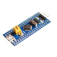
* | * stm board, currently not investigating | ||
* | |||
[[File:Lifepo4.jpg|right|100px]] | [[File:Lifepo4.jpg|right|100px]] | ||
=== LiFePO4 Battery === | === LiFePO4 Battery === | ||
To power the electronics, I plan to use a [https://en.wikipedia.org/wiki/Lithium_iron_phosphate_battery LiFePO4 battery]. | To power the electronics, I plan to use a [https://en.wikipedia.org/wiki/Lithium_iron_phosphate_battery LiFePO4 battery]. | ||
A battery of this type has a voltage of around 3.2V, so it is capable of running the electronics directly, without a voltage regulator. | A battery of this type has a voltage of around 3.2V, so it is capable of running the electronics directly, without a voltage regulator. | ||
It also has a quite large capacity (mAh per gram) and is relatively safe (doesn't catch fire easily, unlike some other lithium battery types). | It also has a quite large capacity (mAh per gram) and is relatively safe (doesn't catch fire easily, unlike some other lithium battery types). | ||
Alternatively, just use a standard 18650 lithium cell and put a diode in series to drop the voltage by about 0.6V. | |||
== Operation == | == Operation == | ||
The basic idea is to indicate whether movement was detected | The basic idea is to indicate whether movement was detected with one minute resolution. | ||
If movement is detected by the PIR, the processor is woken up, it notes the movement in internal memory, goes back to sleep. | |||
At some larger interval, the accumulated data is uploaded, possibly with redundancy to allow for the occasional missed message. | |||
=== time synchronisation algorithm === | |||
It would be nice for the node to know the time, so it can accurately report on time periods where movement was detected. | |||
The LoRaWAN specification has the MAC commands DevTimeReq and DevTimeAns, however they are not supported by TTN yet. | |||
Using them even might give interoperability problems. | |||
To keep the time, we can use the (RTC) onboard the processor/board. | |||
The plan is to synchronize the time using the following algorithm: | |||
To keep the time, we can use the (RTC) onboard the | * in an uplink transmission from the bat box to the network, there is a field containing the UTC time (seconds since 1970/1/1) from the point of view of the bat box | ||
* in | |||
* upon reception (a few seconds later), the network application compares the time field sent by the bat box with the actual time | * upon reception (a few seconds later), the network application compares the time field sent by the bat box with the actual time | ||
* if the difference is beyond some threshold (say | * if the difference is beyond some threshold (say plus/minus 30 seconds), it prepares a down-link transmission with the required offset to correct the time | ||
* when the bat box receives the down-link transmission, it updates its clock with the correction offset. | * when the bat box receives the down-link transmission, it updates its clock with the correction offset. | ||
So, for example if a bat box powers up with no knowledge of the time at all, it'll start at UTC time 0. | So, for example if a bat box powers up with no knowledge of the time at all, it'll start at UTC time 0. | ||
The network application will note a huge time error and prepare a down-link message with the correct offset. | The network application will note a huge time error and prepare a down-link message with the correct offset. | ||
When the | When the node receives the down-link message, it applies the offset to its clock and so updates itself to the correct time. | ||
It doesn't really matter how much time there is between an | It doesn't really matter how much time there is between an uplink and a downlink or when the downlink message is scheduled exactly, since the network sends a time *difference*, not an absolute time. | ||
Downlink messages are only sent when there is a large time error, so they should be relatively infrequent, reducing the network load. | |||
=== message format === | |||
All messages in big endian format. | |||
Uplink (device to network): | |||
* first 4 bytes: timestamp in seconds (since 1970/1/1) | |||
* variable number of bytes: one bit per minute (1 = movement, 0 = no movement) in the past. | |||
Downlink (network to device): | |||
* 4 bytes: time correction value (signed, seconds), positive value means that the device should move its time forward | |||
* 4 bytes: time correction sequence number (to prevent duplicate correction), devices should only accept increasing sequence number | |||
For redundancy, messages can be "overlapping", e.g. send 30 bits presence data (for the past 30 minutes), every 10 minutes. | |||
= | When sending 1 message every 10 minutes, each message contains 4 byte timestamp + 4 byte movement = 8 bytes: | ||
* Using SF9 this fits within the TTN FUP, total 26.64 seconds per day. | |||
* Using SF10 exceeds the FUP by a factor 2 approximately. | |||
* Using SF11 exceeds the FUP by a factor 4 approximately. | |||
== Software == | |||
* | * Arduino firmware: https://github.com/bertrik/lorabatbox | ||
* | * backend Java application: https://github.com/bertrik/motionsensorbackend | ||
== | == External references == | ||
* https://developer.mbed.org/teams/Semtech/code/LoRaWAN-demo-76/ | * https://developer.mbed.org/teams/Semtech/code/LoRaWAN-demo-76/ | ||
* https://www.thethingsnetwork.org/labs/story/a-cheap-stm32-arduino-node | |||
== Future ideas == | == Future ideas == | ||
Challenges and ideas to be implemented in the future: | Challenges and ideas to be implemented in the future: | ||
* find some way to keep the electronics safe from weather, e.g. wrap it all in a kind of silicone pouch | * find some way to keep the electronics safe from weather, e.g. wrap it all in a kind of silicone pouch | ||
* | * use the built-in RTC of the ESP32, use ESP32 low-power sleep | ||
Latest revision as of 12:11, 28 July 2022
| Project LoraBatBox | |
|---|---|
| |
| Monitoring bat boxes with LoRa | |
| Status | Completed |
| Contact | bertrik |
| Last Update | 2022-07-28 |
This page is an idea for adding LoRa capability to a bat box.
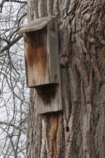
A popular kind of bat box is a flat wooden box with an opening on the bottom and mounted to a tree trunk or building. Bats can use these to sleep during the day (they hunt at night for insects). Some kinds of bats can even use a bat box to raise their young.
To check if a bat box is in use by bats, you can walk up to the tree that the box is mounted on and shine a light into it to see if there are any bats there. But I think it would be nice to investigate if this can be done automatically, without having to go to the individual box and without disturbing the bats with a light!
Update:
Consider this ready-built sensor: https://www.antratek.nl/lorawan-motion-sensor
It appears it already does what this project was planned to do. Senses motion in a 50x50x20 mm box with battery compartment, built-in LoRaWAN antenna, low-power design. Also reports internal temperature and battery level.
This sensor is supported on http://cayenne.mydevices.com
Apparently KPN got this idea now too, using their own network: https://www.overons.kpn/nl/nieuws/2021/innovatieve-toepassing-op-lora-meet-aanwezigheid-beschermde-diersoorten-en-geeft-boost-aan-verduurzaming-woningsector
How to migrate this particular sensor from TTNv2 to TTNv3: https://www.thethingsnetwork.org/forum/t/migrating-tabs-browan-sensors-remote-reboot-to-trigger-otaa/44461
Introduction
The basic idea is to mount some piece of electronics in or on the bat box that monitors if there are any bats in there, by monitoring movement within the bat box. Periodically (say once an hour), detection of movement is broadcast using a LoRaWAN radio transmitter to a central place.
Hardware design
PIR movement detection
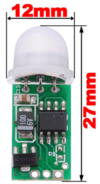
To sense the presence of bats inside the bat box, I plan to use a PIR (passive infrared) detector module which can detect movement of warm bodies. A PIR typically has a low current requirement (say < 0.1 mA), so it can probably be turned on most of the time. Sleeping bats will likely not trigger the movement detection, but that's OK I think, knowing when they enter or leave the bat box is probably enough info.
PIR sensor investigation
I ordered a couple of different mini PIR sensors, so I could do some measurements on which PIR sensor is the 'best', meaning good sensitivity and low quiescent current.
The table below shows some of the properties I measured, including the supply current. Some sensors use a little more when activated, but this was so little that I didn't write it down separately. Also, all sensors I bought seem to have an internal regulator, so every one was fed with 5V, which is then down-regulated to some lower voltage on board the PIR module. This can be a problem because I plan to use a single lithium cell so I have only about 3.2V available.
| Image | Price | Claimed current | Measured current | Onboard regulator | Remarks |
|---|---|---|---|---|---|
 |
USD 1.99 | < 0.1mA | 15 uA | HT7530-1 (3.0V) | probably best candidate to investigate further: probably 3.3V compatible + very low idle current. See also this page, explaining it contains an AS312 PIR sensor, with the electronics on the board basically only doing some voltage regulation |
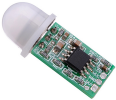 |
USD 2.19 | < 50uA | 1 mA | 7144 (4.4V) | probably worst candidate: high idle current, weird pitch (2mm?) connector, not 3.3V compatible! |
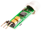 |
USD 1.75 | <60uA | 75 uA | 7133 (3.3V) | aka HC-SR505, it looks like it misses a some part connecting to the OUT pin! |
In relation to being 3.3V compatible, here's a guide on modifying a PIR module for 3.3V.

LoRa / The-Things-Network
I think the LoRa radio technology is perfectly suited as a transmission medium for sending the bat box occupancy data. LoRa has a larger range than similar radio technologies, has relative immunity to narrow-band interference and allows for low-power transmissions. There are already several LoRa gateways provided by the-things-network (TTN) that can receive and forward the data for free (no subscription needed, fair-use policy). If the LoRa network is down for some reason, no harm is done to the bats, possibly just a few days worth of data lost, and I think I can come up with a solution to that.
Microcontroller
I've been considering several boards:
- Heltec lora32 v2, familiar platform (ESP32), has a display, has low-power support in hardware (Vext can be switched off), has a 32 kHz crystal to use with the onboard RTC, however not sure if I can use that with Arduino software
- Heltec Cubecell board, should also be very low power, recently got platformio support
- stm board, currently not investigating

LiFePO4 Battery
To power the electronics, I plan to use a LiFePO4 battery. A battery of this type has a voltage of around 3.2V, so it is capable of running the electronics directly, without a voltage regulator. It also has a quite large capacity (mAh per gram) and is relatively safe (doesn't catch fire easily, unlike some other lithium battery types).
Alternatively, just use a standard 18650 lithium cell and put a diode in series to drop the voltage by about 0.6V.
Operation
The basic idea is to indicate whether movement was detected with one minute resolution. If movement is detected by the PIR, the processor is woken up, it notes the movement in internal memory, goes back to sleep.
At some larger interval, the accumulated data is uploaded, possibly with redundancy to allow for the occasional missed message.
time synchronisation algorithm
It would be nice for the node to know the time, so it can accurately report on time periods where movement was detected.
The LoRaWAN specification has the MAC commands DevTimeReq and DevTimeAns, however they are not supported by TTN yet. Using them even might give interoperability problems.
To keep the time, we can use the (RTC) onboard the processor/board. The plan is to synchronize the time using the following algorithm:
- in an uplink transmission from the bat box to the network, there is a field containing the UTC time (seconds since 1970/1/1) from the point of view of the bat box
- upon reception (a few seconds later), the network application compares the time field sent by the bat box with the actual time
- if the difference is beyond some threshold (say plus/minus 30 seconds), it prepares a down-link transmission with the required offset to correct the time
- when the bat box receives the down-link transmission, it updates its clock with the correction offset.
So, for example if a bat box powers up with no knowledge of the time at all, it'll start at UTC time 0. The network application will note a huge time error and prepare a down-link message with the correct offset. When the node receives the down-link message, it applies the offset to its clock and so updates itself to the correct time. It doesn't really matter how much time there is between an uplink and a downlink or when the downlink message is scheduled exactly, since the network sends a time *difference*, not an absolute time. Downlink messages are only sent when there is a large time error, so they should be relatively infrequent, reducing the network load.
message format
All messages in big endian format.
Uplink (device to network):
- first 4 bytes: timestamp in seconds (since 1970/1/1)
- variable number of bytes: one bit per minute (1 = movement, 0 = no movement) in the past.
Downlink (network to device):
- 4 bytes: time correction value (signed, seconds), positive value means that the device should move its time forward
- 4 bytes: time correction sequence number (to prevent duplicate correction), devices should only accept increasing sequence number
For redundancy, messages can be "overlapping", e.g. send 30 bits presence data (for the past 30 minutes), every 10 minutes.
When sending 1 message every 10 minutes, each message contains 4 byte timestamp + 4 byte movement = 8 bytes:
- Using SF9 this fits within the TTN FUP, total 26.64 seconds per day.
- Using SF10 exceeds the FUP by a factor 2 approximately.
- Using SF11 exceeds the FUP by a factor 4 approximately.
Software
- Arduino firmware: https://github.com/bertrik/lorabatbox
- backend Java application: https://github.com/bertrik/motionsensorbackend
External references
- https://developer.mbed.org/teams/Semtech/code/LoRaWAN-demo-76/
- https://www.thethingsnetwork.org/labs/story/a-cheap-stm32-arduino-node
Future ideas
Challenges and ideas to be implemented in the future:
- find some way to keep the electronics safe from weather, e.g. wrap it all in a kind of silicone pouch
- use the built-in RTC of the ESP32, use ESP32 low-power sleep