RemoteResetArduino: Difference between revisions
No edit summary |
No edit summary |
||
| (3 intermediate revisions by the same user not shown) | |||
| Line 1: | Line 1: | ||
{{Project | {{Project | ||
|Name=RemoteResetArduino | |Name=RemoteResetArduino | ||
|Status= | |Status=Completed | ||
|Contact=FooBar | |Contact=User:FooBar | ||
}} | }} | ||
| Line 23: | Line 23: | ||
* Connect the arduino to a usb port on a working system (I used a openwrt based router). | * Connect the arduino to a usb port on a working system (I used a openwrt based router). | ||
* Connect the digital pins to the power and reset lines on an ATX mainboard. | * Connect the digital pins to the power and reset lines on an ATX mainboard. | ||
** Lookup which pins to use in your manual, or look at the board. From the 2 pins for pwrbtn and reset, you need the 3.3v powered pin, not the ground pin | |||
* Make sure the arduino ground is connected to a ground on the pc mainboard | |||
* Make a serial connection to the arduino (115200 baud) | * Make a serial connection to the arduino (115200 baud) | ||
* Configure the pin-numbers (see 'help' command, use 'config' command) | * Configure the pin-numbers (see 'help' command, use 'config' command) | ||
| Line 28: | Line 30: | ||
** Force will hold the (power) button for 4 seconds, reset and power only simulate a short press | ** Force will hold the (power) button for 4 seconds, reset and power only simulate a short press | ||
* Use the 'check #' command to see if a system is powered on | * Use the 'check #' command to see if a system is powered on | ||
== Pinout On the ATX Board == | |||
On my Asrock boards, the pinout for the 'system panel header' is as follows: | |||
* PLED+ PLED- PWRBTN GND | |||
* HDLED+ HDLED- GND RESET DUMMY | |||
== Pictures == | == Pictures == | ||
Latest revision as of 20:10, 20 August 2013
| Project RemoteResetArduino | |
|---|---|
| Status | Completed |
| Contact | User:FooBar |
| Last Update | 2013-08-20 |
Summary
An arduino program to toggle power and reset buttons on standard ATX PC's, and to read the status of the machine (Powered on or off, Power present @ PSU).
Introduction
I was building a 3-node cluster to test some cluster-filesystems for a client, and used 'wake-on-lan' to remotely boot the various cluster nodes when needed. This worked somewhat, but I was unable to reboot a hanging system, or see if a wake-on-lan packet actually arrived at the system.
Doing some tests with a firmata sketch on an arduino proved that I could easily toggle the powerbutton and resetbutton on an ATX mainboard, bringing this project to life.
Code
The code can be found on https://github.com/sigio/remotereset-arduino
Working
- Connect the arduino to a usb port on a working system (I used a openwrt based router).
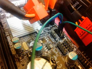
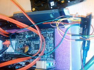
- Connect the digital pins to the power and reset lines on an ATX mainboard.
- Lookup which pins to use in your manual, or look at the board. From the 2 pins for pwrbtn and reset, you need the 3.3v powered pin, not the ground pin
- Make sure the arduino ground is connected to a ground on the pc mainboard
- Make a serial connection to the arduino (115200 baud)
- Configure the pin-numbers (see 'help' command, use 'config' command)
- Toggle reset and/or power buttons with commands 'reset #', 'power #' or 'force #'
- Force will hold the (power) button for 4 seconds, reset and power only simulate a short press
- Use the 'check #' command to see if a system is powered on
Pinout On the ATX Board
On my Asrock boards, the pinout for the 'system panel header' is as follows:
- PLED+ PLED- PWRBTN GND
- HDLED+ HDLED- GND RESET DUMMY
Pictures
Usage Session Example
> RemoteReset-Arduino started

> help

Help:
 config      Edit configuration
   config [0-7] resetpin pwrpin name
 reset #     Toggle reset switch on config #
 power #     Toggle power switch on config #
 force #     Long-Press power switch on pc number #
 erase #     Erase config number #
 state       Check power state
 dump        Dump configuration to serial
 save        Save configuration to EEPROM
 load        Load configuration from EEPROM
 wipe        Wipe onfiguration and update EEPROM

> dump

Config
Config: 0    Data: 0 / 255 / 255 / unused
Config: 1    Data: 1 / 7 / 6 / gluster1
Config: 2    Data: 1 / 3 / 2 / gluster2
Config: 3    Data: 1 / 4 / 5 / gluster3
Config: 4    Data: 0 / 255 / 255 / unused
Config: 5    Data: 0 / 255 / 255 / unused
Config: 6    Data: 0 / 255 / 255 / unused
Config: 7    Data: 0 / 255 / 255 / unused

> power 1

Sending power signal to pin: 6

