DecodingLora: Difference between revisions
No edit summary |
No edit summary |
||
| (40 intermediate revisions by 2 users not shown) | |||
| Line 1: | Line 1: | ||
{{Project | |||
| Name=DecodingLora | |||
| Status=Completed | |||
| Contact=bertrik | |||
| Picture=DecodingLora_Project.jpg | |||
}} | |||
This page is about understanding the LoRa RF modulation format. | This page is about understanding the LoRa RF modulation format. | ||
| Line 14: | Line 15: | ||
A concrete result could be that someone writes software which makes it possible to receive and decode LoRa signals with a cheap software defined radio, like rtlsdr. | A concrete result could be that someone writes software which makes it possible to receive and decode LoRa signals with a cheap software defined radio, like rtlsdr. | ||
== Status == | |||
* 2016-05-08: can no longer get either sdrangel nor rtl-sdranglelove to compile: sdrangel needs a newer cmake than my distro provides (and building cmake from source is very cumbersome), rtl-sdrangelove needs some qt5 multimedia package that I forgot how to install | |||
* 2016-02-19: ran into this patent [https://www.google.com/patents/EP2763321A1?cl=en EP2763321], it explains a lot of the details investigated here, like the symbol encoding, interleaving method | |||
* 2016-02-16: can no longer get a decode to work with rtl-sdrangelove (something changed), sdrangel still works | |||
* 2016-01-17: decoded a transmission from an RFM95 module in software using sdrangelove lora plugin (just use the right settings ...) | |||
Work done on decoding LoRa by other people: | |||
* [https://myriadrf.org/blog/lora-modem-limesdr A nice explanation and set of GnuRadio blocks] | |||
* [http://www.jailbreaksecuritysummit.com/s/Reversing-Lora-Knight.pdf a paper on reverse engineering LoRa by Matt Knight] | |||
* [https://github.com/rpp0/gr-lora github repository with GNURadio blocks for receiving LoRa modulated radio messages using SDR] by Pieter Robyns | |||
== Modulation basics == | == Modulation basics == | ||
The LoRa modulation appears to be defined by the following parameters: | The LoRa modulation appears to be defined by the following basic parameters: | ||
* the bandwidth BW, meaning the difference in minimum and maximum frequency | * the bandwidth BW, meaning the difference in minimum and maximum frequency | ||
* the spreading factor SF, this is a measure for the number of bits encoded per symbol | * the spreading factor SF, this is a measure for the number of bits encoded per symbol | ||
* the coding rate CR, this is a measure for the amount of forward error correction | * the coding rate CR, this is a measure for the amount of forward error correction | ||
Additionally the following settings can be changed: | |||
* preamble length and SyncWord value | |||
* whether an explicit header is sent with the message, this header contains information about the parameter of the rest of the message (payload length, the CR parameter, CRC presence) | |||
* presence of a 16-bit CRC | |||
* the LowDataRateOptimization bit (DE) | |||
On the air I have seen the following waveforms: | On the air I have seen the following waveforms: | ||
* a series of up-chirps at the start of a message (preamble) | * a series of up-chirps at the start of a message (preamble), the number of up-chirps corresponds to the PreambleLength registers | ||
* two up-chirps with a chirp-phase corresponding to the contents of the SyncWord register | |||
* two down-chirps at the end of the preamble (sync-pattern) | * two down-chirps at the end of the preamble (sync-pattern) | ||
* data-chirps, these consist only of up-chirps (like the preamble), but with a jump in the "phase"/timing of the chirp. The frequency shift of this jump likely encodes one symbol representing several data bits (SF bits per symbol). | * data-chirps, these consist only of up-chirps (like the preamble), but with a jump in the "phase"/timing of the chirp. The frequency shift of this jump likely encodes one symbol representing several data bits (SF bits per symbol). | ||
| Line 37: | Line 55: | ||
At the top of the spectrogram you see the data portion of the signal, consisting solely of up-chirps. | At the top of the spectrogram you see the data portion of the signal, consisting solely of up-chirps. | ||
Since the LoRa signal is basically a single carrier being swept over a certain bandwidth in a specific way, it is possible to recover the frequency by FM demodulation of the signal generated by a Semtech chip | Since the LoRa signal is basically a single carrier being swept over a certain bandwidth in a specific way, it is possible to recover the frequency by FM demodulation of the signal generated by a Semtech chip. This allows for a more compact representation of the signal for analysis. | ||
The approach used on this page is to receive the LoRa signal with an inexpensive rtlsdr receiver, FM-demodulate it in SDR-application qgrx and record the resulting output in the audio application Audacity. | |||
Some thoughts on analysis: | |||
* For simplicity, the output length of the forward error coding parameter CR can be chosen to be equal to the symbol size SF. This way each 4-bit input nibble should result in exactly one output symbol. For example use CR=4/6 with SF=6, CR=4/7 with SF=7, CR=4/8 with SF=8, | |||
* make the payload equal to the PRNG sequence, such that the whitening effect of the PRNG is cancelled out, possibly making analysis easier. | |||
* vary the payload with a walking-bit sequence, so the shuffling order of the interleaver can be analysed. | |||
=== payload contents === | |||
[[File:audacity_bw0_cr4_sf8.png|thumb|right]] | |||
The image on the right shows the audio captured in audacity from an FM-demodulated LoRa-signal (with settings BW=8kHz, CR=4/8, SF=8, implicit mode, 1-byte payload), with the single-byte changed from 0x00 (top) to 0xFF (bottom). | |||
In the highlighted area, some differences can be seen between the FM-waveforms. | In the highlighted area, some differences can be seen between the FM-waveforms. | ||
=== preamble length === | |||
Some experimentation shows that when the preamble length n is set to 0 through the register interface, we still see 2 up-chirps and 2 down-chirps (plus 1/4th of a up-chirp) in the preamble on-air. | Some experimentation shows that when the preamble length n is set to 0 through the register interface, we still see 2 up-chirps and 2 down-chirps (plus 1/4th of a up-chirp) in the preamble on-air. | ||
This is consistent with the preamble timing formula in the datasheet, which states that the preamble is (n + 4.25) symbols long. | This is consistent with the preamble timing formula in the datasheet, which states that the preamble is (n + 4.25) symbols long. | ||
Actually the final two up-chirps in the preamble encode for the 'SyncWord'. | |||
=== sync word === | |||
[[File:Lora syncword.png|thumb|right]] | |||
Something that is not mentioned in the RFM95 datasheet, but is mentioned in the SX1276 datasheet, is the SyncWord setting in register 0x39. The datasheet mentions a default setting of 0x12 and a LoRaWAN setting of 0x34. | |||
Modifying this setting results in the following changes to the FM waveform just before the reverse chirps. From top to bottom: 0x00, 0x12, 0x34, 0xFF. | |||
It seems the setting influences the "starting value" of the two chirps just before the reverse chirps. | |||
The starting value appears to be closely related to the low nibble of the sync word (with 0xF corresponding to half the symbol time). | |||
This setting only has influence on the preamble/sync, there is no influence on the rest of the packet. | |||
=== CRC === | |||
[[File:Lora_crc.png|thumb|right]] | |||
The datasheet suggests that CRC can be turned off and on through bit RxPayloadCrcOn (mistake in datasheet: Rx should be TX?) in register RegModemConfig2 (0x1E). | |||
The image on the right shows the effect of turning it off (top) and on (bottom). | |||
Oddly enough, this doesn't seem to influence the length of the transmission. | |||
Settings: BW=8,CR=4/8,SF=8, 1 byte payload (0x00). | |||
=== Header === | |||
[[File:Lora_header.png|thumb|right]] | |||
A header can be specified. This header tells the receiving end about the length of the payload, presence of CRC and coding rate of the rest of the message. The header itself is encoded with a coding rate CR=4/8. | |||
The image on the right shows the effect of turning it on (top) and off (bottom). | |||
The difference in length is about 8.4 symbols. | |||
Settings: BW=8,CR=4/8,SF=8, 1 byte payload (0x00). | |||
=== Payload size === | |||
[[File:Lora_payload.png|thumb|right]] | |||
The image on the right shows the FM-demodulated signal with varying payload. A payload size of 1 (0x00) on top and a payload size of 2 (0x00 0x00) on the bottom. | |||
Curiously, the size of the transmission is exactly the same. | |||
=== LowDataRateOptimize bit === | |||
[[File:Lora_lowdatarate.png|thumb|right]] | |||
[[File:Lora_lowdatarate4.png|thumb|right]] | |||
[[File:LoRa_spectrum.png|thumb|right]] | |||
Register 0x26, bit 3 contains a LowDataRateOptimize setting, which should have some influence on the number of payload symbols transmitted according to the datasheets. | |||
The image on the right shows the effect of turning it off (top) and on (bottom) | |||
Settings: BW=8,CR=4/8,SF=8, 1 byte payload (0x00), implicit mode, no CRC. | |||
The image below it shows the effect of turning it off (top) and on (bottom) with the same settings, except now a payload of 4 bytes 0x00. | |||
So, I see no difference in over-the-air length with payloads of 1 and 4 bytes when this bit is modified. | |||
== The timing formula == | |||
In paragraph 4.1.1.7 of the SX1276 datasheet, the time on air for a LoRa packet is discussed. | |||
This is derived from the symbol time (2^SF / BW), the number of preamble symbols and number of payload symbols. | |||
A lot of information on the packet structure and the effect of certain parameters can be obtained from the formula that gives the number of payload symbols: | |||
[[File:Lora_timing.png|center]] | |||
Parameters: | |||
* PL: number of payload bytes | |||
* SF: spreading factor | |||
* CRC: presence of a CRC (0 if absent, 1 if present, I assume) | |||
* IH: whether the header is enabled (0 if enabled, 1 if disabled) | |||
* DE: whether low data rate optimization is on (0 if disabled, 1 if enabled) | |||
* CR: the coding rate (1 meaning 4/5 rate, 4 meaning 4/8 rate) | |||
What we can derive from this formula: | |||
* there are always at least 8 payload symbols in a packet, and these are completely independent of parameters like PL, SF, CR, etc. | |||
* the upper part of the fraction under the ceil() function expresses a number of *bits* (because PL, number of payload bytes, is multiplied by 8) | |||
* the CRC is 16 bits long | |||
* the difference in length between implicit and explicit header mode is 20 bits | |||
* the number calculated under the ceil() expresses a number of *nibbles*, since it divides by SF (number of bits/symbol) and the factor 4 (4 bits/nibble). | |||
* when low data rate optimization DE is turned on, the number of bits encoded in each symbol (nominally SF) is reduced by 2. | |||
== Recordings == | |||
See [http://bertrik.sikken.nl/sdr/ here] for some IQ recordings of the LoRa signal. | |||
The filenames contain a code for the LoRa modulation setting which was used for each recording. | |||
This should mostly be obvious. For example, a postfix of BW21CR48SF6PL64x00 means the following: | |||
* BW21: Bandwidth is approximately 21 kHz (20.8 actually) | |||
* CR48: Code rate is 4/8 | |||
* SF6: Spreading factor is 6 | |||
* PL64x00: Payload is 64 bytes of 0x00 | |||
The files were recorded on ms windows using sdr# v1.0.0.1111 at a sample rate of 1024 kHz. | |||
== Decoding in software == | |||
There exists a LoRa plug-in for the SDR application sdrangelove. | |||
This plug-in is able to decode (with varying success) the payload from a LoRa message with the following settings: | |||
* BW = 8, SF = 8, CR = 4/6, DE = 1 (LowDataRateOptimization=on) | |||
The code for the SDR application sdrangelove with the LoRa plugin can be found | |||
[https://github.com/hexameron/rtl-sdrangelove here] | |||
To build it: | |||
* get the code from github with git clone | |||
* cmake . | |||
* make | |||
Code for driving a HopeRF RFM95 module from a 3.3V 8MHz Arduino mini pro can be found | |||
[https://github.com/bertrik/loratest here (in loratest.ino)] | |||
This code is configured with the settings mentioned earlier. | |||
This code uses my [https://github.com/bertrik/RadioHead clone of the RadioHead library] to control the RFM95. | |||
=== Algorithmic steps === | |||
The LoRa plugin appears to perform the following steps (in this order): | |||
* decode the chirp phase | |||
* undo the whitening sequence by XORing again with the PRNG | |||
* undo the interleaving | |||
* undo the forward error coding | |||
== External links == | == External links == | ||
* [http://www.hoperf.com/upload/rf/RFM95_96_97_98W.pdf RFM95 datasheet] | * Datasheets: | ||
* A nice explanation of the preamble and data modulation at [http://www.link-labs.com/what-is-lora/ link-labs] | ** [http://www.hoperf.com/upload/rf/RFM95_96_97_98W.pdf RFM95 datasheet] | ||
* Semtech [http://www.semtech.com/ | ** Semtech [http://www.semtech.com/images/datasheet/an1200.22.pdf AN1200.22] Lora modulation basics | ||
* rtl-sdrangelove | * Background: | ||
* [https://github.com/hexameron/rtl-sdrangelove/tree/master/plugins/channel/lora hexameron github] | ** A nice explanation of the preamble and data modulation at [http://www.link-labs.com/what-is-lora/ link-labs] | ||
** The [https://www.google.com/patents/US7791415 US7791415] patent, which describes mostly the structure of the transmitter side. | |||
** The [https://www.google.com/patents/EP2763321A1 EP2763321] patent, which describes both the general frame structure and modulation method | |||
** [http://leobodnar.com/balloons/files/LoRa/LoRa-2.gif Annotated analysis of the LoRa signal] by Leo Bodnar, clearly showing the preamble, preamble-end-marker and the data bits | |||
* Tools: | |||
** Semtech [http://www.semtech.com/apps/filedown/down.php?file=SX1272LoRaCalculatorSetup1%271.zip LoRa Calculator], allows you to play with modulation parameters and see the impact on symbol time, sensitivity etc. | |||
* Code: | |||
** rtl-sdrangelove lora plugin on [https://github.com/f4exb/sdrangel/tree/master/plugins/channel/lora f4exb github] | |||
** rtl-sdrangel lora plugin on [https://github.com/hexameron/rtl-sdrangelove/tree/master/plugins/channel/lora hexameron github] | |||
Latest revision as of 13:17, 11 May 2020
| Project DecodingLora | |
|---|---|
| |
| Status | Completed |
| Contact | bertrik |
| Last Update | 2020-05-11 |
This page is about understanding the LoRa RF modulation format.
LoRa is an abbreviation of Long Range, meaning it is an radio modulation format that gives longer range than straight FSK modulation. This is achieved by a combination of methods: it uses a spread spectrum technique called Chirp Spread Spectrum (CSS) and it uses forward error coding (in combination with whitening and interleaving).
To transmit or receive LoRa signals, you need to buy hardware that supports this modulation format.
The goal of this project is to collect more detailed information on the LoRa modulation and packet format. A concrete result could be that someone writes software which makes it possible to receive and decode LoRa signals with a cheap software defined radio, like rtlsdr.
Status
- 2016-05-08: can no longer get either sdrangel nor rtl-sdranglelove to compile: sdrangel needs a newer cmake than my distro provides (and building cmake from source is very cumbersome), rtl-sdrangelove needs some qt5 multimedia package that I forgot how to install
- 2016-02-19: ran into this patent EP2763321, it explains a lot of the details investigated here, like the symbol encoding, interleaving method
- 2016-02-16: can no longer get a decode to work with rtl-sdrangelove (something changed), sdrangel still works
- 2016-01-17: decoded a transmission from an RFM95 module in software using sdrangelove lora plugin (just use the right settings ...)
Work done on decoding LoRa by other people:
- A nice explanation and set of GnuRadio blocks
- a paper on reverse engineering LoRa by Matt Knight
- github repository with GNURadio blocks for receiving LoRa modulated radio messages using SDR by Pieter Robyns
Modulation basics
The LoRa modulation appears to be defined by the following basic parameters:
- the bandwidth BW, meaning the difference in minimum and maximum frequency
- the spreading factor SF, this is a measure for the number of bits encoded per symbol
- the coding rate CR, this is a measure for the amount of forward error correction
Additionally the following settings can be changed:
- preamble length and SyncWord value
- whether an explicit header is sent with the message, this header contains information about the parameter of the rest of the message (payload length, the CR parameter, CRC presence)
- presence of a 16-bit CRC
- the LowDataRateOptimization bit (DE)
On the air I have seen the following waveforms:
- a series of up-chirps at the start of a message (preamble), the number of up-chirps corresponds to the PreambleLength registers
- two up-chirps with a chirp-phase corresponding to the contents of the SyncWord register
- two down-chirps at the end of the preamble (sync-pattern)
- data-chirps, these consist only of up-chirps (like the preamble), but with a jump in the "phase"/timing of the chirp. The frequency shift of this jump likely encodes one symbol representing several data bits (SF bits per symbol).
One symbol has a length in time of (2^SF)/BW. Chirps seem to have a constant chirp rate for a specific modulation setting, both when going up and down. When the frequency of a chirp reaches the end of the band, it "wraps around" to the other side. One chirp nominally covers the entire bandwidth BW once during one symbol time.
Investigation
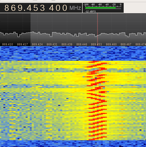
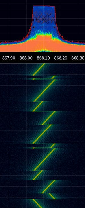
The image on the right shows the LoRa spectrogram for a short message as recorded by gqrx, when sending a 1-byte payload (with settings SF=12,BW=8,CR=4/8, implicit header). At the bottom of the spectrogram you can see the preamble consisting of 10 up-chirps and 2 down-chirps. At the top of the spectrogram you see the data portion of the signal, consisting solely of up-chirps.
Since the LoRa signal is basically a single carrier being swept over a certain bandwidth in a specific way, it is possible to recover the frequency by FM demodulation of the signal generated by a Semtech chip. This allows for a more compact representation of the signal for analysis.
The approach used on this page is to receive the LoRa signal with an inexpensive rtlsdr receiver, FM-demodulate it in SDR-application qgrx and record the resulting output in the audio application Audacity.
Some thoughts on analysis:
- For simplicity, the output length of the forward error coding parameter CR can be chosen to be equal to the symbol size SF. This way each 4-bit input nibble should result in exactly one output symbol. For example use CR=4/6 with SF=6, CR=4/7 with SF=7, CR=4/8 with SF=8,
- make the payload equal to the PRNG sequence, such that the whitening effect of the PRNG is cancelled out, possibly making analysis easier.
- vary the payload with a walking-bit sequence, so the shuffling order of the interleaver can be analysed.
payload contents
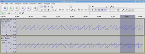
The image on the right shows the audio captured in audacity from an FM-demodulated LoRa-signal (with settings BW=8kHz, CR=4/8, SF=8, implicit mode, 1-byte payload), with the single-byte changed from 0x00 (top) to 0xFF (bottom). In the highlighted area, some differences can be seen between the FM-waveforms.
preamble length
Some experimentation shows that when the preamble length n is set to 0 through the register interface, we still see 2 up-chirps and 2 down-chirps (plus 1/4th of a up-chirp) in the preamble on-air. This is consistent with the preamble timing formula in the datasheet, which states that the preamble is (n + 4.25) symbols long.
Actually the final two up-chirps in the preamble encode for the 'SyncWord'.
sync word
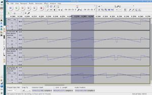
Something that is not mentioned in the RFM95 datasheet, but is mentioned in the SX1276 datasheet, is the SyncWord setting in register 0x39. The datasheet mentions a default setting of 0x12 and a LoRaWAN setting of 0x34.
Modifying this setting results in the following changes to the FM waveform just before the reverse chirps. From top to bottom: 0x00, 0x12, 0x34, 0xFF. It seems the setting influences the "starting value" of the two chirps just before the reverse chirps. The starting value appears to be closely related to the low nibble of the sync word (with 0xF corresponding to half the symbol time).
This setting only has influence on the preamble/sync, there is no influence on the rest of the packet.
CRC
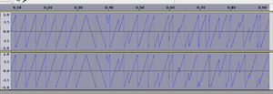
The datasheet suggests that CRC can be turned off and on through bit RxPayloadCrcOn (mistake in datasheet: Rx should be TX?) in register RegModemConfig2 (0x1E). The image on the right shows the effect of turning it off (top) and on (bottom).
Oddly enough, this doesn't seem to influence the length of the transmission.
Settings: BW=8,CR=4/8,SF=8, 1 byte payload (0x00).
Header

A header can be specified. This header tells the receiving end about the length of the payload, presence of CRC and coding rate of the rest of the message. The header itself is encoded with a coding rate CR=4/8.
The image on the right shows the effect of turning it on (top) and off (bottom).
The difference in length is about 8.4 symbols.
Settings: BW=8,CR=4/8,SF=8, 1 byte payload (0x00).
Payload size

The image on the right shows the FM-demodulated signal with varying payload. A payload size of 1 (0x00) on top and a payload size of 2 (0x00 0x00) on the bottom.
Curiously, the size of the transmission is exactly the same.
LowDataRateOptimize bit


Register 0x26, bit 3 contains a LowDataRateOptimize setting, which should have some influence on the number of payload symbols transmitted according to the datasheets.
The image on the right shows the effect of turning it off (top) and on (bottom) Settings: BW=8,CR=4/8,SF=8, 1 byte payload (0x00), implicit mode, no CRC.
The image below it shows the effect of turning it off (top) and on (bottom) with the same settings, except now a payload of 4 bytes 0x00.
So, I see no difference in over-the-air length with payloads of 1 and 4 bytes when this bit is modified.
The timing formula
In paragraph 4.1.1.7 of the SX1276 datasheet, the time on air for a LoRa packet is discussed. This is derived from the symbol time (2^SF / BW), the number of preamble symbols and number of payload symbols.
A lot of information on the packet structure and the effect of certain parameters can be obtained from the formula that gives the number of payload symbols:

Parameters:
- PL: number of payload bytes
- SF: spreading factor
- CRC: presence of a CRC (0 if absent, 1 if present, I assume)
- IH: whether the header is enabled (0 if enabled, 1 if disabled)
- DE: whether low data rate optimization is on (0 if disabled, 1 if enabled)
- CR: the coding rate (1 meaning 4/5 rate, 4 meaning 4/8 rate)
What we can derive from this formula:
- there are always at least 8 payload symbols in a packet, and these are completely independent of parameters like PL, SF, CR, etc.
- the upper part of the fraction under the ceil() function expresses a number of *bits* (because PL, number of payload bytes, is multiplied by 8)
- the CRC is 16 bits long
- the difference in length between implicit and explicit header mode is 20 bits
- the number calculated under the ceil() expresses a number of *nibbles*, since it divides by SF (number of bits/symbol) and the factor 4 (4 bits/nibble).
- when low data rate optimization DE is turned on, the number of bits encoded in each symbol (nominally SF) is reduced by 2.
Recordings
See here for some IQ recordings of the LoRa signal.
The filenames contain a code for the LoRa modulation setting which was used for each recording. This should mostly be obvious. For example, a postfix of BW21CR48SF6PL64x00 means the following:
- BW21: Bandwidth is approximately 21 kHz (20.8 actually)
- CR48: Code rate is 4/8
- SF6: Spreading factor is 6
- PL64x00: Payload is 64 bytes of 0x00
The files were recorded on ms windows using sdr# v1.0.0.1111 at a sample rate of 1024 kHz.
Decoding in software
There exists a LoRa plug-in for the SDR application sdrangelove. This plug-in is able to decode (with varying success) the payload from a LoRa message with the following settings:
- BW = 8, SF = 8, CR = 4/6, DE = 1 (LowDataRateOptimization=on)
The code for the SDR application sdrangelove with the LoRa plugin can be found here To build it:
- get the code from github with git clone
- cmake .
- make
Code for driving a HopeRF RFM95 module from a 3.3V 8MHz Arduino mini pro can be found here (in loratest.ino) This code is configured with the settings mentioned earlier. This code uses my clone of the RadioHead library to control the RFM95.
Algorithmic steps
The LoRa plugin appears to perform the following steps (in this order):
- decode the chirp phase
- undo the whitening sequence by XORing again with the PRNG
- undo the interleaving
- undo the forward error coding
External links
- Datasheets:
- RFM95 datasheet
- Semtech AN1200.22 Lora modulation basics
- Background:
- A nice explanation of the preamble and data modulation at link-labs
- The US7791415 patent, which describes mostly the structure of the transmitter side.
- The EP2763321 patent, which describes both the general frame structure and modulation method
- Annotated analysis of the LoRa signal by Leo Bodnar, clearly showing the preamble, preamble-end-marker and the data bits
- Tools:
- Semtech LoRa Calculator, allows you to play with modulation parameters and see the impact on symbol time, sensitivity etc.
- Code:
- rtl-sdrangelove lora plugin on f4exb github
- rtl-sdrangel lora plugin on hexameron github